ADAU1701 has Noise but changeing PLL filter will be gone. why?
Hello Gens,
I have developed a PCB of ADAU1701 with I2S AMP. Everything is good from input analog singal. However, there is noise from ADAU1701.
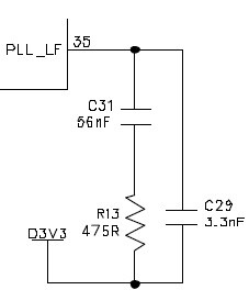
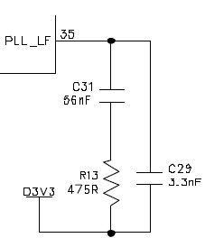
I found the problem seems from Jitter or somewhere relative PLL. The original PLL filte is 3.3nF, 475ohm and 56nF. The noise will be gone when I remove 475ohm and replaced by a cap 0.1uF. does everyone know the problem from? I set PLL to 256Fs and 12.288Mhz XTAL.
Audio Signal Processors
SigmaDSP Audio Processors
adau1701
Hello,
Your question is likely for the gurus at ADI, however perhaps this post may at least get things started, even if my help is only generic. The standard PLL features pole-zero compensation, with a zero at around 6KHz:
Replacing the resistor with a 0.1uF cap changes this filter to dominant-pole compensation. Your revised filter results in reduced jitter and phase noise (since the PLL's VCO can no longer change its frequency quickly), but at the expense of increased difficulty locking and a longer lock time. Since you're getting satisfactory operation with this filter, your PLL is in fact locking and remaining stable. You may find, however, that in production some units run fine while others won't lock. Then again, you may find they all work OK.
You may wish to compare your PCB layout with the best practices advice at
https://ez.analog.com/docs/DOC-1889
The PLL is one of the most sensitive areas of a SigmaDSP layout; those filter components must be right at the chip without intervening vias. Given a choice, it would be better to fix any issues with the layout than modifying the filter.
Best regards,
Bob
Thanks, Bob!
Jason,
It would be very helpful for us if we could review your schematic and pcb layout. If you are not comfortable posting them in this public forum, we can start a private discussion and review your work offline.
BR,
Coleman
Thanks, Bob.
I have read your link. However, it seems no big help. I have made several PCB of ADAU1701. This one
is the 1st PCB with I2S AMP then met this problem. I think it is jitter. Therefore, I am thinking to find which
signal has this jitter then I would like to add some cap to add another signal slow down to match.
Hello Coleman,
I am good to offer you circuit and portion of layout but not here.
Can you give me your mail then I can provide to you? I hope you guys can give me more idea to solve this issues.
I have started an private discussion so we can consult about your schematic and settings.
Best regards,
Coleman
Hello,
I've got the exact same problem. Did you manage to solve it?
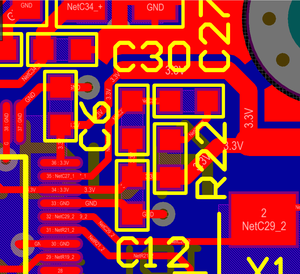
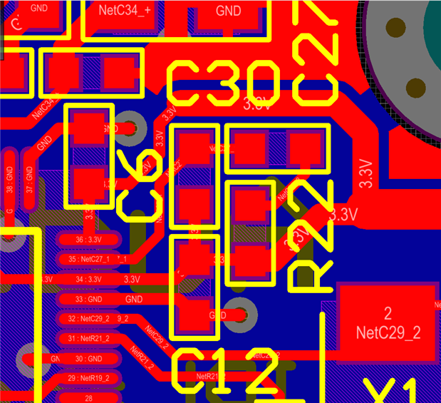
Here's my layout of the PLL filter:
Cheers,
Jack
Hi Jack,
Your layout looks fine from this picture. You have confirmed the RC values in the filter? And you have the same symptom, where you swap the 475R with a 0.1 uF and the problem goes away? Can you quantify the noise that you are experiencing? Thanks.
Regards,
Coleman
This question has been assumed as answered either offline via email or with a multi-part answer. This question has now been closed out. If you have an inquiry related to this topic please post a new question in the applicable product forum.
Thank you,
EZ Admin
Please log in to reply.