FIR Filters and required Coefficients
I'm trying to get an understanding of FIR filters and their benefits over other types of filters, since my knowledge of DSP fundamentals is still a work in progress. For example, I want to have a simple pass band of 200 Hz to about 6 KHz for part of my application with sharp edges to the response. I understand that a FIR filter provides very sharp edges, but beyond that I don't understand enough about DSP's to grasp what other benefit this filter type offers beyond some of the other filter types in SigmaStudio. After reading numerous posts, I understand I could overlap several General bi-quad filters to create a very steep roll-off at each edge of the passband. Wouldn't this achieve the same result or does it come down to the efficiency of resources required in SigmaStudio? My project is utilizing the 1701.
Any insight would be appreciated.
Hi Byron,
We don't have a lot of expertise in FIR filter design, which is partly why there isn't an FIR filter designer tool integrated into SigmaStudio. FIR filters can, in some cases, have distinct advantages over IIR filters in that they can be designed to have specific magnitude responses as well as specific phase responses. IIR filters, on the other hand, are generally accompanied by phase distortion, which is hard to avoid, but they can be very efficient in terms of the amount of memory resources they require.
Most customers who use the FIR filter in SigmaStudio end up using some third-party tool (like Matlab) to generate the proper coefficients.
Sorry that I can't provide more insight! Perhaps another forum member can share information if they have an opinion about this.
Hi Byron,
Brett's answer sums up the relative strengths of FIR and IIR filters quite succinctly. As he said, you can do rather extraordinary things with FIR, but IIR filters are less trouble. They do have a nonlinear phase response, however most ears (mine, anyway) are fortunately rather insensitive to phase distortion.
The frequency band of interest significantly affects the choice between these filter types -- and the two frequencies you mentioned are far enough apart that you could try one of each.
In case you haven't come across it in your research, a really good DSP resource is available here:
http://www.analog.com/en/content/scientist_engineers_guide/fca.html
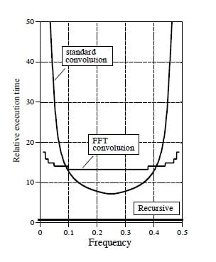
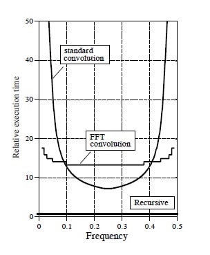
This graph from page 348 of Steven W. Smith's book shows that while IIR (recursive) filters work with about the same efficiency over the DSP's frequency range, FIR (standard convolution) filters are most efficient near the middle. The frequency range is normalized to the sample rate fs, as is always done in DSP texts:
Your 6KHz roll-off normalizes to 0.125 (assuming fs = 48K), which falls within the efficient range for FIR filters. On the other hand, 200 Hz normalizes to 0.004 -- there the FIR filter takes way too much time to execute. Execution time corresponds to the FIR filter's length (number of taps), which in SigmaDSP relates to the number of instructions and data memory the filter needs. This says don't even try a 200 Hz FIR filter. Use one or more double-precision filters in series, as you mentioned they can have overlapping responses to form one unified sharp filter. AD has a filter design tool for analog active filters that can be used to generate the cutoff frequency and Q for each filter section, see near the bottom of this discussion for more info:
http://ez.analog.com/message/66356#66356
While you can also use a IIR filter for the 6KHz lowpass, this one is possible in FIR. As Brett mentioned, many folks use a program like MATLAB to figure the kernel (list of coefficients) for a FIR filter. If you have the time and a sense of adventure, it's not impossible to calculate FIR coefficients yourself -- and you'll gain some valuable insight into how these things work. Chapter 16 of the above-mentioned book describes the windowed-sinc method. It takes only a simple BASIC program or even a spreadsheet to calculate the coefficients, which you could then copy into the coefficient table of a SigmaDSP FIR filter. Have fun!
Bob
Thanks for the insight guys. It looks like I can achieve what I want by simply doing the cascading of 4 or 5 low pass plus 4 to 5 high pass filters to get the necessary sharp roll-off (got this idea from one of your other posts Bob.......thanks again). Designing these will be easy. Having never dealt with IIR or FIR filters, I didn't know if they inherently had some other benefit I should be aware of. I'm not quite ready to tackle the coefficient calculations just now until I get the basic functionality up and running.........then I'll attempt to have some fun as you say. Starting to read through the DSP reference material you talked about here and in several posts Bob, but it's going to take some time to wrap my head around it as I consider myself to be a DSP and SigmaStudio novice yet.
I was also understanding based on another post that IIR filters can be troublesome in that they don't decay to a amplitude of zero which can allow some signal to still be present when there is no input signal. This would be horrible in my application depending on level.
Hi Byron,
I wouldn't expect the IIR filters to have unwanted output with no input, as long as you use double-precision filters.
Bob
Bob, agreed. The fixed-point architecture of the SigmaDSP means that the IIR impulse response tails off to zero pretty quickly due to rounding.
Brett, thanks for your insight on the IIR filter response. So that's why they settle so nicely, even when a feedback coefficient approaches 1.0 (as might happen for bass boost). Thus in this case, rounding error plays nice.
Byron, your question caused me to re-evaluate a previous design which needed a 3.5KHz lowpass, down about -30dB at 4KHz to meet FCC telephone specs. The original design was a 13 pole Chebyshev IIR -- six General second order blocks and a first order. The high Qs in that filter produced a nasty-looking phase response, so I just tried a FIR filter with 55 taps (limited by available instructions). This has only a 13dB loss at 4KHz. The FIR filter would need way more instructions to make spec.
Bob
Hi Byron and all,
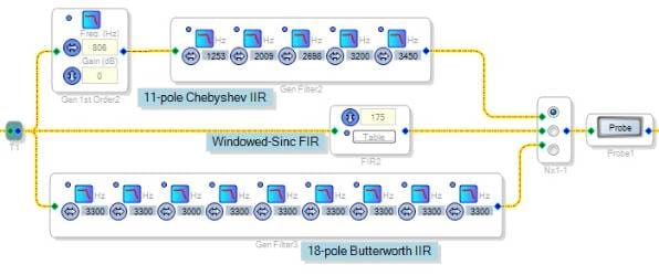
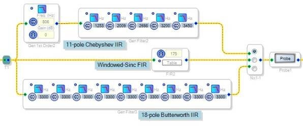
The attached project compares three implementations of a FCC-compliant telephone filter, which must achieve about 30 dB down at 4KHz. The -3dB point is not specified -- so a sharper filter can preserve more speech bandwidth. Our previous products used a 5-pole, 3.1 KHz Chebychev active filter. With SigmaDSP, we were able to extend the -3dB response to 3.5KHz.
On top is the 11-pole Chebyshev that's presently designed in. Next is a 175-tap linear-phase FIR filter. I calculated its coefficients with the attached spreadsheet. Matlab would of course be quicker and easier for many, but it would take me a month to figure it out after several months to pay for it! Finally, there's a 18-pole Butterworth filter.
Running speech from a podcast, I could hear no difference between the filters -- that's to say, they sound equally lousy. It's telephone bandwidth after all. So I might as well stay with the Chebyshev filter, which uses fewer instructions by far. Hopefully my musings here will save someone with similar requirements some trouble.
Best regards,
Bob
Please log in to reply.