A Poor Engineer's Distortion Analyzer
Yes, there are poor engineers. Where I work audio is a sideline, so we do not yet have a dedicated distortion analyzer. I've been toying with buying a used one on eBay, but it's interesting to see what can be done with just a ADAU1701 evaluation board and SigmaStudio.
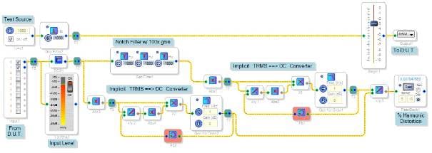
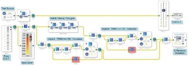
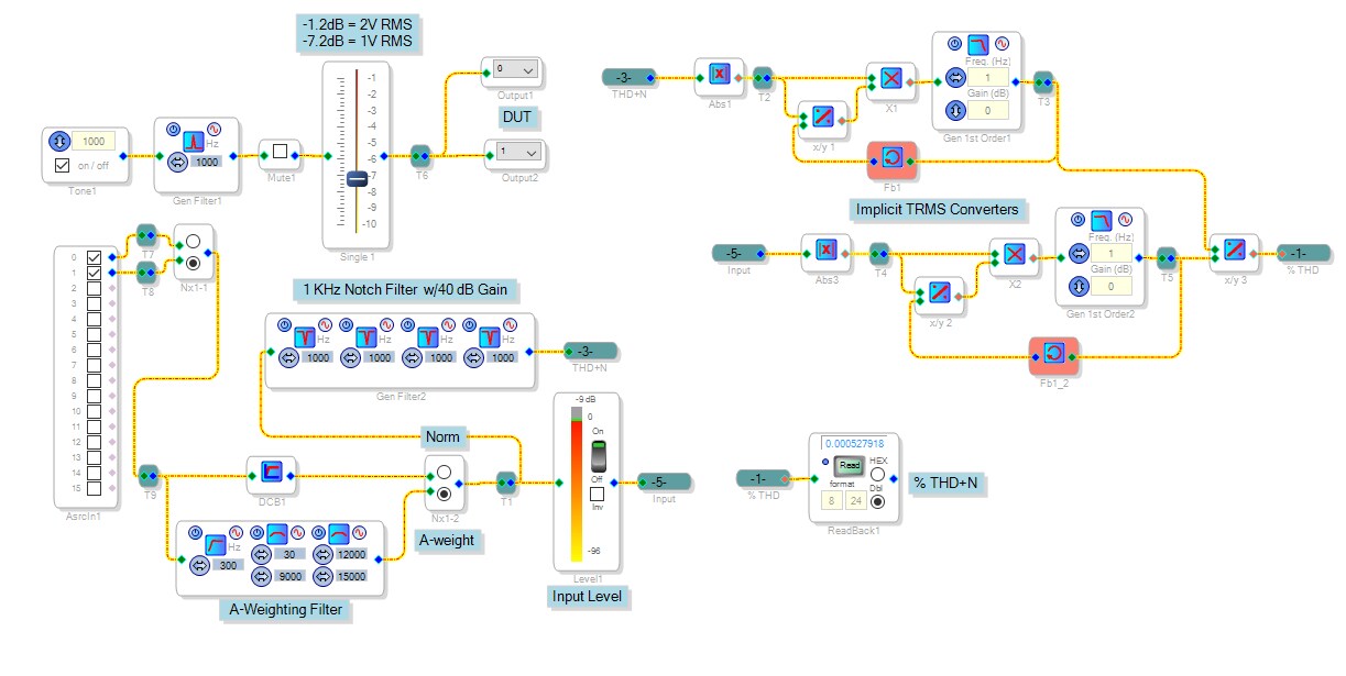
As shown, this signal flow drives the device under test with a 1000 Hz tone. In turn that device outputs the tone along with harmonics and noise. The ADC samples this and the DSP notches out the tone, leaving the rest. Then it's compared with the tone level to calculate:
THD+N % = 100 * ((Distortion + Noise) / (Signal + Distortion + Noise)
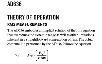
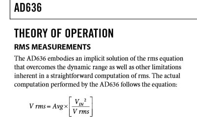
Accurately reading the signal and the noise requires true RMS measurements. SigmaStudio has some RMS-responding blocks, but they're described as "approximate". Thus my distortion analyzer uses built-from-scratch RMS to DC converters. These converters are quite noteworthy in themselves -- they employ an implicit method I shamelessly lifted from the venerable AD636 analog RMS-DC converter IC. That chip is still around after 30+ years because it works so well! A snippet from its data sheet explains implicit RMS conversion:
This analyzer is of course limited by the -1701's own THD. A direct connection from DAC out to ADC in reads 0.007%, so under ideal conditions you can measure down to about 0.01%. Ideal conditions mean keeping the -1701's input and output levels near, but not right at, their maximums. Thus you may need to improvise pads to operate your tested device at its desired levels. Also I recommend running SigmaStudio on a laptop under battery power. Finally, note that the sine wave output (from the DAC) is common grounded to the analyzer input (the ADC). Thus, bridged power amplifiers could only be tested one side at a time. It may be possible to use both input ADCs in a differential mode, but this was not tried. Of course you'll definitely need some serious external attenuation to route that output into the -1701. If you use a separate pure 1KHz source, you'll need to tune it carefully (as with the old analyzers I've seen on eBay).
A PA mixer (not studio quality) tested with this analyzer measured 0.04% distortion normally, and 0.05% when driven into compression. It always sounded OK to me, but now I know exactly how it performs!
Message was edited to include note on common-ground.
Audio Signal Processors
ad636
distortion_analyzer
Analog Functions
rms_converter
SigmaDSP Audio Processors
implicit
adau1701
RMS to DC Converters
Show More
Thanks, Bob! Do you mind if we put this in the wiki's collection of example projects?
Hi Brett,
Please feel free to place it on the wiki. BTW -- when I try to edit the wiki it appears as HTML code. Is that normal?
Bob
Hi Bob,
The wiki uses a kind of proprietary syntax. There is a full explanation of it here: https://wiki.analog.com/wiki/help
You can look at the formatting of existing pages to see how it works.
There's also a playground page where you can try making edits without the risk of messing up an existing page: https://wiki.analog.com/playground/playground
Hi Brett,
Thanks for your help with the wiki. I added this discussion to the list of useful EZ threads.
Bob
Great! I just approved your page edit.
As it turns out, there is a difficulty with the implicit TRMS ==> DC converters in the project shown above. The standard divide block for Sigma100 DSPs (-1701, etc.) loses its accuracy for divisors below 0.0625 (see Re: 1701 division block). Since this condition may occur within the converters, their accuracy cannot be guaranteed. Thus, the implicit RMS converters need to be replaced with standard envelope average converters as shown below:
The output divider poses no problem since its divisor is the strength of the overall signal, expected to be greater than 0.0625.
With this change the residual distortion reads at about 0.025%, thus it's suitable only for rough measurements.
Bob
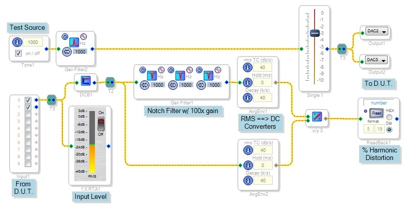
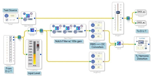
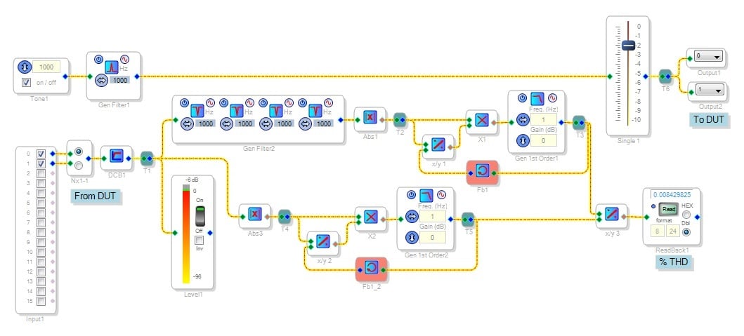
The ADAU1452 includes hardware divide via base-2 logs, and its mini eval board runs an external codec with active DAC filters. The original "poor engineer's distortion analyzer" with implicit TRMS converters runs fine on this one. Residual THD is 0.085% 0.0085%.
Bob:
Nice work!
What I would like to do is make this self booting AND allow external frequency control via an I2C command/data.
Regards,
TomC
Hello TomC,
Depending upon your requirements, it may be easier to choose several fixed frequency filters and oscillators via GPIO selection, which would thus avoid loading filter coefficients yourself. To go with I2C control, you can have your microcontroller compute and/or lookup the needed filter coefficients using the formulas given at General 2nd Order [Analog Devices Wiki] BrettG made a spreadsheet for EQ coefficients, I expanded it to include shelf filters, find it at https://ez.analog.com/message/160192#160192. I could probably expand it further to include notch filters if you think this would help.
Self-booting the ADAU1452 eval board is easy enough. I've talked to a ADAU1701 from a PIC microcontroller, but have no similar experience with controlling a ADAU1452 via I2C. Thus I'm afraid I'm of no help with that part of your design.
Best regards,
Bob
Hello,
I just added notch filters to the spreadsheet, you'll find it at:
https://ez.analog.com/message/204505#204505
Bob
I gues to obtain values in %% 100 multiplication needed.
Sorry, I did not notice 40 dB filter gain.
Hello Bob:
Thank you again for your work.
I am working on the design and benchmarking the performance of this D.A..
On a related note, are Gerber files of the 1452 eval board available?
Thank you,
Tom
Hi Tom,
Judging from this thread:
https://ez.analog.com/message/179869#179869
AD has been willing to provide these in the past. Try starting a new similar thread and see what happens.
I'm using the PEDA as we speak, as where I work we have a new mixer prototype and nothing else with which to test it!
Best regards,
Bob
Bob:
Thanks! I trust the PEDA is giving satisfactory results!
TomC
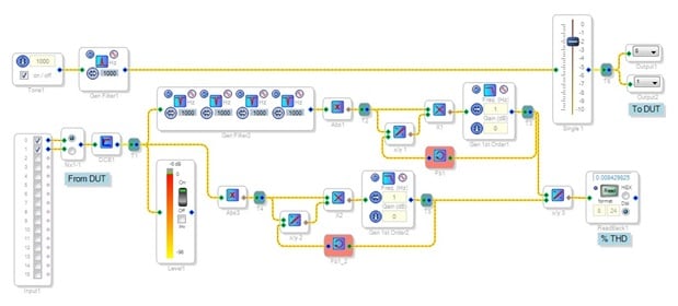
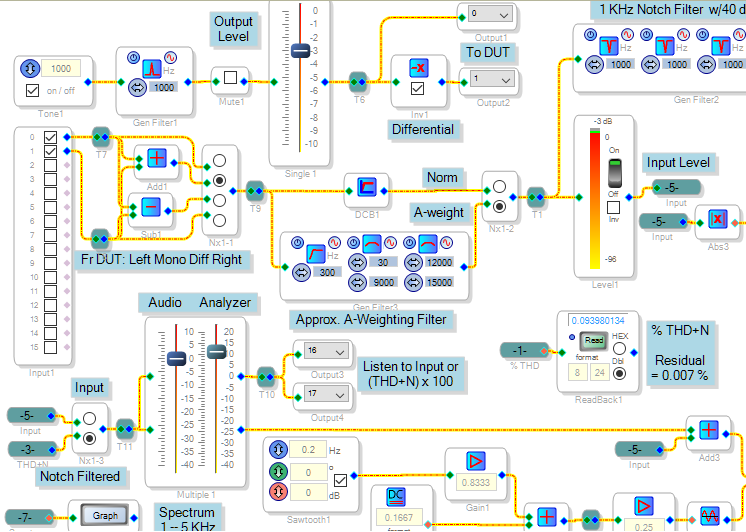
Having some recent use for this project, I added a few features:
Differential input and output
Headphone output to listen to the filtered distortion products
Approx. A-weighting filter
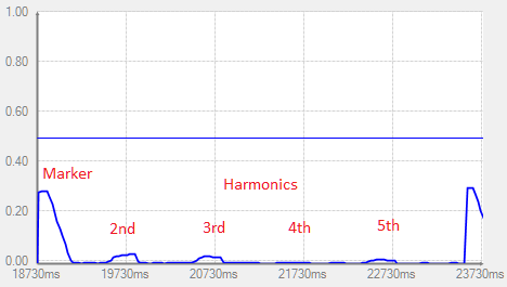
A display of the first five harmonic amplitudes
The latter is modeled after a simple RF spectrum analyzer, not around the -1452's FFT capability (which no one seems to know how to use anyway).
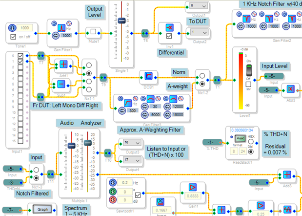
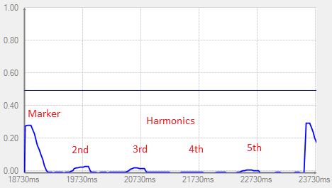
As you can see above, the mixer I was checking out has just under 0.1% THD+N. At left, the harmonics from 2nd to 5th are shown.
Hi Bob, thanks again for sharing this with us!
Really interesting to have the ability to monitor the distortion product.
@ADI I would like to see some documentations around the FFT functionality

Heidi,
Thanks for your appreciation! I found that listening to the THD+N products is fascinating as well. It sound nothing like the pure tone input! And it may provide a clue to the distortion's origin.
I notice in your schematic a distortion reading that's lower than the residual readings I get by routing the tone output directly back to the analyzer input. Which DSP are you using?
Best regards,
Bob
Bob,
it is a prototyp around the 1452.
In case it sounds like the pure tone input, maybe it is related to a psychoacoustic effect (missing fundamental) and of cause a good harmonic distortion spectrum.
Mine does not sound like the pure tone input, you can hear the 3k if you rise the multiplier. But in this case, the overall noise is dominant and the 3k is in the background. The measurement was taken by a "normal" desktop pc, so maybe there is some influence.
Best regards,
Lasse
This was the DUT. Next stepp is to test a distortion analyzer based on a sharc+.
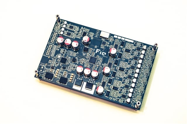
Nice looking prototype! And its performance appears to exceed that of a stock -1452 board.
Bob
Thanks Bob
It utilized a ADC/CS5381 and DAC/CS4398 in differential configuration. Clock is a crystek cchd at 24,576mhz with a clock distribution buffer. All mlck inputs a driven by a single low phase noise clock.
The THD+N must be near/equal to the specs, but i have no acess to an analyzer that is able to measure it, and like the topic, I‘m not able to afford an AP/R&S with adequate performence.
Maybe today i would choose a different ADC/DAC, but it is still not that simple to beat their specs.
Please log in to reply.