Powering up 1701mini board from external supply.
Hello guys!
Just a short question, I have got a 1701mini board and yesterday I built a 3.3v power supply. I would like to test, whether it is good enough to power up the 1701 processor. So what I want is to bypass the on-board linear regulator and power up the board from my external supply. The simplest idea is to solder a wire to the output of the on-board linear regulator, but what I do not know is how that regulator will behave if it is switched off and an external voltage is applied to its output. So if somebody, who knows the "anatomy" of the on-board linear regulator might tell me, whether it would be fine to simply solder an external wire to its output and apply my 3.3v, or I have to do something else, to power up the whole 1701mini board from my external supply?
Thanks in advance!
P.S. I am sorry if this question is kind of stupid, the idea is, I am not an engineer, my major at the Uni is piano performance, so in terms of electronics I am self-taught and do not have much experience also.
Hello Skfir,
There are no stupid questions, though sometimes there are stupid answers. I hope mine isn't one of them.
The good news is, I just tried the connection you described, and it works. The bad news is, I'm afraid to unequivocally recommend it.
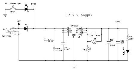
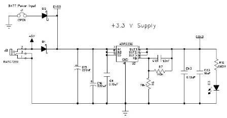
First of all, it would be a whole lot easier if you build your supply for 5.0 volts and plug it into J2. That would require no modification to the board (other than populating J1). It would power the whole board, including the Class D amplifier. It would also make the friendly applications engineers at AD happier. Perhaps, however, your available power won't allow for that, and you don't need the Class-D amp.
Garden-variety linear regulators blow up at the mention of applied output voltage (install a 7805 backwards and you'll see). The AD3336 is quite a different beast, with a PNP pass transistor in a common-emitter configuration. Its data sheet does not mention the possibility of Vout > Vin, but neither did it recommend an input-output reverse protection diode. So far, so good.
Soldering a wire to the ground side of J2 was easy. Not so much with the 3.3V connection to the positive side of C23.
After soldering the wires, I measured 3.26 volts across them (from U2) in normal operation. Then I pulled J3 to kill 5V power from the USB. After confirming the polarity of my external supply, I connected it with alligator clips to the two soldered wires on the board. The -1701 fired up (not literally). It accepted a Link-Compile-Download and ran a simple tone generator which confirmed audio output. Current drain from the external 3.3V supply measured 108 mA. What worries me is the input side of U2, which now measures 2.5V -- indicating that it's allowing some current from output to input. Hopefully that's from internal protection. This may attempt to power the class-D amp, so be sure that remains disabled. With the external power supply operating I unplugged the USBi ribbon cable from the eval board's header, and the sound continued. One final caveat: your 3.3V supply needs to be adequately regulated and filtered to get the best low-noise performance from the -1701.
With this experiment over, I plugged everything back normally and nothing was worse for wear. BTW -- I had always assumed you were studying EE. You do engineering better than I play piano.
Best regards,
Bob
Thanks so much again, Bob!
Sure I have a 5v supply and 3.6 also (thanks to the low-drop on ADP3336) just the thing is in some not too much distant future I am planning to leave the eval board in peace and make my own board, with all the other things I need already there. For this sake I built the 3.3 supply. The reason why I want to test it is simple - I wanted to try ADP2371, but could not find any LFCSP_WD - DIP adapter, so do not know how to try them. So I decided to try an IC from LT, but since I have some bad experience with LT's linear ICs which turned out to be not at all so linear, I want to try it first. If everything works fine, I can power 1701 right from there and it will save some space on the board, so just want to try to see what happens. Of course if I could get a kind of
LFCSP_WD-DIP adapter the choice would be obvious, since I am in deep love with AD products at all. Soldering should not be a problem, at least I hope so, since I am a pianist I can even manually solder 201 resistors quite fine. Thanks again for help!
P.S. I am really merely a pianist, just want to help one blind person, that is why I do all this ultrasonic stuff.
Thanks for doing this experiment, Bob. I don't have a lot of in-depth knowledge of LDOs, but I know enough to be able to agree with your assessment.
Skfir, another option if you are really planning on "retiring" the evaluation board would be to lift the OUT1, OUT2, and OUT3 pins on the ADP3336 so that they no longer contact the landing pads. That hack isn't too difficult to do - but it's difficult to reverse it! Once pins have been bent a few times, they have a tendency of detaching themselves from the package.
Hi Brett!
Yeah, I thought about that as well, but you know, since I am a student and the board costs quite a bit, I do not want it to "retire" really. Just want to try for several minutes to see whether my supply is good enough.
Actually I remember when I almost completed the first prototype, everything worked, I, with pleased face switch off the power, and accidentally my hand shakes, touches the board and its output runs directly into the 400v electrostatic transducer pin.... Sparkle... Silence... $200... Ha-ha, so after that with my student budget I try to be very careful. Guys, one more question, what is acceptable supply ripple for decent stable work of the 1701?
I know this is off topic but I couldnt resist lol
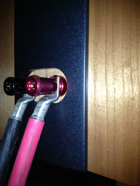
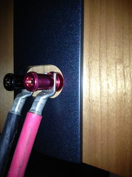
10 gauge Bob? im running 2 gauge
Hi Skfir,
Like many engineering questions, the answer here is, "it depends." If you're running studio-quality audio and wish to keep it that way, you'll want as quiet a power supply as possible (it seems like everything in audio is overkill, that explains stuff like 10-gauge speaker cable!). If you just need it to work, more ripple is allowable. For more info see this post, https://ez.analog.com/message/71716#71716
Bob
Got it! Thanks Bob!
Please log in to reply.