adau 1701 project and USBi
Hi all,
i have problem with my firs own project with adau 1701. I made two boards but both not working. When i comile project and try to send project to the dsp (with analog usbi) i receive error message with no conecting board and in rigt corner of IDE is "download failed". I check power supply on every pin (include 1,8V) and everythink looks ok. Power supply give me 3,27V. I found one mistake reset generator have switched pin "VCC" and "MR". I am alredy correct mistake and change IC for new one but still PCB doesnt work. So i try check comunication (I2C) between USBi and board but i can not see anythink on the osciloscope. Now i thinking about USBi if is it okay. I receive USBi with ad1940 eval board which is using SPI for comunication.
Thanks for any advice.
Regards
Jiri Skalny
ad1940
Audio Signal Processors
SigmaDSP Audio Processors
Hi Jiri,
The USBi is equipped with both interfaces and is the same for the ADAU1701 and ADAU1940 boards, see this app note: https://www.analog.com/static/imported-files/application_notes/AN-1006.pdf
I tested the USBi from a -1940 eval board with a -1701 board, it worked fine. So we can eliminate any difference in the USBi as the source of the com problem. Some other possibilities:
The hardware configuration for your -1701 based project should look like this (add the self-boot EEPROM if used):
Check your crystal oscillator if you haven't already. This is sensitive to layout, see:
https://ez.analog.com/message/33074#33074
Best regards,
Bob

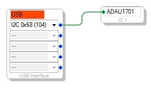
Hi Jiri,
A quick search on this forum brought up another possible difficulty, in case you're using an existing 1.8V supply for the DSP core instead of the -1701's internal regulator and transistor: The -1701 data sheet says, "If the regulator is not used in the design, VDRIVE can be tied to ground." It should say, "If the regulator is not used in the design, the VDRIVE pin must be tied to ground." See BrettG's post at:
https://ez.analog.com/message/21733#21733
Bob
Thanks for your input, Bob!
You are correct; the USBi that ships with ADAU1701 boards is the same as the one shipped with AD1940 boards.
Yes, the VDRIVE pin must be grounded if the 1.8 V core voltage is externally supplied.
Thanks,
Brett
Hi Bob,
thank you for the tips. Finally I found a bug. I did not have conected eprom to I2C bus. It is a little strange for me but now it is going... I have one last (i hope) question. When i try GPIO and conected rotary encoder to the board through connector it was not working. When i conect encoder (with same program and configuration) before 100R resistor it was going to work. So my question is: is the schematic correct (now i mean only GPIO)?
Thanks,
Jiri
Hi Jiri,
When you refer to the rotary encoder... do you mean that you're using the GPIO circuitry board that was included with the evaluation board?
Hi BrettG,
no i am using my own encoder but i make it like recommended which is described in this document: http://www.analog.com/static/imported-files/application_notes/AN-951.pdf
Have nice day,
Jiri
OK. I believe those 10 kOhm resistors are used to limit the amount of current going into the GPIO pin. You could lower the value of those resistors, but I would recommend still keeping the resistors connected. Perhaps the rotary encoder manufacturer has a recommended applications circuit?
Ok. I will try to use only push buttons. The encoder is remained after some repairs avreceiver.
This question has been assumed as answered either offline via email or with a multi-part answer. This question has now been closed out. If you have an inquiry related to this topic please post a new question in the applicable product forum.
Thank you,
EZ Admin
Please log in to reply.