adau1701 serial input and internal adc-dac problem
Hi
I use I2S codec in slave mode, as specified in the datasheet:
-If an external ADC is connected as a slave to the ADAU1701,
use both the input and output port clocks. The OUTPUT_LRCLK
(MP10) and OUTPUT_BCLK (MP11) pins must be set to master
mode and connected externally to the INPUT_LRCLK (MP4)
and INPUT_BCLK (MP5) pins as well as to the external ADC
clock input pins. The data is output from the external ADC into
the SigmaDSP on one of the four SDATA_INx pins (MP0 to MP3).
Why internal ADC and a DAC at this time don't work?
As soon as I tear OUTPUT_LRCLK - INPUT_LRCLK
or OUTPUT_BCLK and INPUT_BCLK internal ADC and DAC start working (I2S codec does not work)
Is this normal??
Thanks
Audio Signal Processors
SigmaDSP Audio Processors
adau1701
Hi Yuran-n,
I apologize that your question has not been addressed yet. Recently somebody pointed me to this thread since it was still open - I must have not noticed when you originally posted! Sorry for the long delay.
I think I understand your question. Basically, you have the ADAU1701 set up with its serial output in master mode, and you're wondering why you need to connect the clocks to the ADAU1701's serial input side as well. The answer is that the ADAU1701's serial input has no option for master mode. It is always a slave.
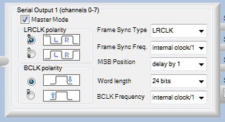
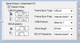
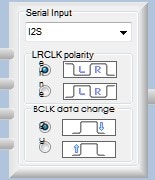
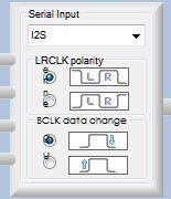
You can see this in the register window:
Serial Output:
Serial Input:
Note that the serial output control box has a checkbox for Master Mode, whereas the serial input side does not.
In order to run the serial input as a master, you must also run the serial output as a master, and then connect the LRCLK and BCLK signals externally between the serial output and the serial input.
I hope this makes sense. Let me know if you have any other questions.
hello BrettG
Excuse for my bad English
Everything was simple
Internal and external ADС/DAС
can work at the same time together only with a frequency of 48 KHZ.
And I wanted to include on 96 KHZ.
Thanks
In order to change the sample rate of the system, please follow these directions:
This question has been assumed as answered either offline via email or with a multi-part answer. This question has now been closed out. If you have an inquiry related to this topic please post a new question in the applicable product forum.
Thank you,
EZ Admin
Please log in to reply.