ADAU1701 Aux ADC Readback
Hi,
I've got a system running in which a micro polls a readback cell in Sigma to read back the current level read on the Aux ADC. This is from an external microphone pre-amp and mic.
I'm currently generating a number of sine tones, and reading off the mic values a number of times per tone, so I can do some averaging within the micro (this will probably change to an rms block at some point).
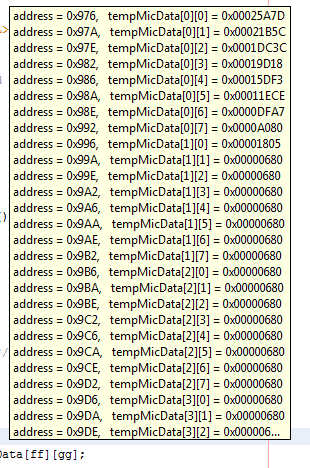
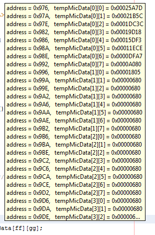
The problem I'm having is that the aux adc starts returning a static value after a few reads. There's no set number of reads I can do before it starts reading the same value. The following screenshot indicates this better -
It can be seen that I can manage 9 reads of the aux adc readback block before it starts returning a repeated value. 9 is not set either, sometimes it's less, sometimes more. I've debugged the i2c bus with my scope as much as I can, and nothing is locking up, it's just returning exactly the same value from the DSP each time.
Are there any glaring things I'm doing wrong?
Audio Signal Processors
adc
aux
SigmaDSP Audio Processors
adau1701
readback
Show More
Hello,
There's a few posts here about using the aux ADCs for audio that may help you troubleshoot the problem:
https://ez.analog.com/message/29430#29430
https://ez.analog.com/thread/18664
Have you looked directly at the aux ADC input pin with a scope? The signal from your preamp could be dying down from a capacitor charging (the aux ADC needs a 1.5V DC midpoint with the signal riding on top, in the range of 0 to 3.0 volts p-p). You could also try this test: In your project, connect an unused audio DAC to the aux ADC output (the same spot where you're reading back to the uC), then view the corresponding output pin with a scope.
Best regards,
Bob
Hello njt,
I think it looks like you're basically hitting the lower limit of the ADC. Remember, the auxiliary ADCs are only 8-bit. That means they only detect 256 discrete levels over the range of 0 V to 3 V. In other words, the step size is only 3 / 256 = 11.7 mV. That's quite a large step!
In comparison, the normal audio ADCs are 24-bit, which means they detect 16.7 million discrete levels. Much better!
So, the auxiliary ADC has an 8-bit ADC, but that maps to a 24-bit number. How does that work? Well, basically the 8 bits of ADC data map to the top 8 bits, and the remaining bits are filled with zeros.
Since we use two's complement to represent data in SigmaDSPs, actually the maximum value is one LSB short of the full 24 bits, so you end up getting just below 24 bits of data.
A full-scale signal should basically look like this: 0x7FFFFF, but since only the top 8 bits are used, you get 0x7F0000.
This means that the smallest step (one LSB above zero) should be about 0x010000.
So, anything you get below 0x010000 is basically the smallest signal the aux ADC can handle.
I think there is a bit of dither in the circuit, so you might see levels lower than 0x010000, but anything below that is just in the noise floor anyway.
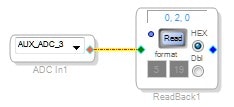
I did a quick test on the evaluation board and here is what I got.
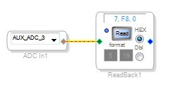
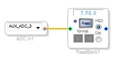
With the potentiometer fully open, I got 7, F8, 0. Note that the bottom 4 bits are left out... this should read 7, F8, 00. So, this is very close to my expected maximum value of 7FF00.
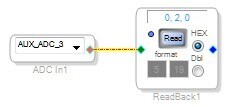
For the minimum test, I expect a minimum of 00100. My results with the potentiometer fully closed are here:
So, I expected 00100, and I got 00200. That's only one LSB of difference. So, it works!
In any case, if your signal goes below this level, you won't get a valid reading. It's simply a question of the ADC's accuracy, and since this ADC was intended for reading DC levels in control applications (and never intended for audio), the accuracy is very poor.
Please log in to reply.