Cheap square root via "op-amp"
SigmaStudio's square root block provides an immediate sample-to-sample output. Because it must come up with a result for every sample, however, it uses many instructions. If your application needs a square-root function in a slower path -- perhaps in the envelope processing of a compressor's side chain, or for a measurement -- you can implement a slow, but accurate, square root with far fewer instructions using the "op-amp" inversion technique shown here. This may have other uses, too.
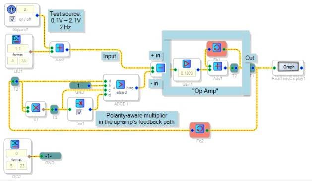
Analog designers are used to building functions by placing the "opposite" function in the feedback loop of an op-amp. For example, using a diode with a more-or-less exponential V-I characteristic in that feedback loop produces a logarithmic function. You can do the same in SigmaDSP, with its op-amp block. Oops, you have to make the op-amp block yourself, but it's easy. It's shown inside the blue box in the schematic below.
As shown this "op-amp" has differential inputs, zero offset, and infinite DC gain -- not bad at all. Its gain ramps down at a steady 6dB / octave to a respectable 10,000 at 0.1 Hz. It is unity-gain stable. In short, easy to use except for one condition: You must give it a proper feedback loop at all times. Hardware op-amps usually just "hit the rail" without consequences when driven that way, but this one overflows the DSP in that case. Thus you must watch your input level, and make your feedback loop work without polarity reversal at all times.
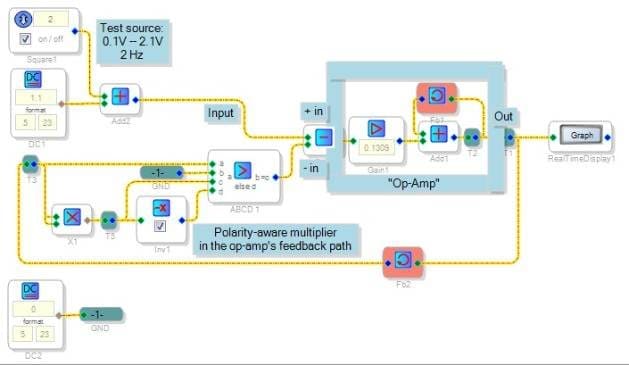
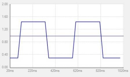
The above circuit uses a multiplier to square its input signal. Placing that inside the "op-amp" feedback loop yields a square root. The logic around the multiplier makes it work the same way for positive and negative inputs, to keep everything sane as described above. The thing looks complicated but uses 65 instructions, of which 38 are for the test signal source and real-time display. The square-rooter itself uses only 27 instructions. The down side is that it takes many samples to respond to a changed input, but that may be quite acceptable in some applications. The response below appears clean -- no overshoot.
This idea may work to produce other "expensive" functions by inverting the corresponding "cheap" one, with the limitations discussed above.
square_root
op-amp
invert_function
operational_amplifier
feedback_loop

Hi Bob,
This is really, really cool! Maybe we can integrate this into a new cell and make it slightly more instruction-efficient. I will suggest that to Miguel.
Hi Bob,
I understand the basic way that this circuit works, but why did you choose the value of 0.1309 in the gain block inside the "op amp"? Should that be user-controllable, or a fixed value? Where did the value come from?
Thanks!
Brett
Hi Brett and Miguel,
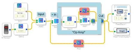
The op-amp's internal loss (a gain < 1.0) helps to keep it stable. Your thoughtful question led me to run a sort of standard op-amp stability test, with unity-feedback. Hardware op-amps are often used this way to buffer high-impedance signals, but here of course it's only useful for testing:
The added noise is to perturb the thing into instability, should it want to do that. It appears quite stable with unity internal gain as shown. However, change that gain to 2.0 and it takes off into uncontrolled oscillation. This shows there's an upper limit to the usable internal gain. The analysis is beyond me, but I would suspect that the loop gain (the internal gain times any gain in the external feedback path) should stay less than unity to guarantee stability.
Clearly there's no need to use this "op-amp" to produce straight gain, or to invert a filter response to get an opposite response -- since all that is directly available in SigmaDSP. The use I envision is to invert nonlinear functions at low frequency. Often such nonlinear functions have an unexpected gain. For example, the square-rooter needs a square function (x^2) in op-amp's feedback path. Since the square function is nonlinear, its small-signal gain varies according to its DC operating point. We can define that gain as the derivative d/dx (x^2), which is 2x. Thus the square function's small-signal gain increases directly with input. In turn, the square-rooter's maximum loop gain is experienced with a full scale input (roughly 16), where its output would be 4, and the feedback gain would be 2(4) = 8. To guarantee stability with this worst-case input, I suspect the internal "op-amp" gain should be 1/8 = 0.125. I had used a slightly higher gain in the original circuit above, not having thought of this until your question. Surprisingly I went back and tested the original square-rooter with a full-scale input and could not get it to oscillate with the slightly excessive gain. Thus my thinking may be a bit conservative.
I got the original, strange-looking gain value by setting the op-amp's gain at 1 Hz to 1000. The op-amp works as a faster version of the integrator shown at https://ez.analog.com/thread/16674. Thus its gain is best though of as a time constant. To set a 1Hz gain of K, the time constant has to be T = 1/(2 pi K). The corresponding internal gain G is:
G = 1/(T fs) = (2 pi K) / fs
With K = 1000 and fs = 48000, G = 0.1309
Actually there's no need to have a "neat" number (like 1000) for K. Thus you might make G selectable between several choices. Perhaps powers of (1/2) between 1/2 and 1/32 would be suitable. Users would set the highest internal gain that's stable in their application, yielding in turn the fastest possible settling time. This is like compensating a hardware op-amp.
Just as with a hardware op-amp, this block is capable of extreme gain near DC. It can easily be thrown into overflow with ill-defined inputs or poorly-designed feedback. Thus output bounds checking could be quite useful if it doesn't add too many instructions.
Bob
A footnote: SigmaStudio Beta 3.9 includes a square root approximation block which uses fewer instructions than the others.
Please log in to reply.