control 2nd order filter freq. from external POT on aux_adc
I think this should be simple but I have not found how to do this.
Looked through AN951 andthe posting to date and can not see this. Maybe I have missed it as it seems a basic application.
I need to implement a variable frequency 2nd order low pass filter from a liner pot connected to one of the aux_adc pins on a ADAU1701.
I found the General (2nd Order/Lookup) filter and set it up with the required filter curves. To test this filter Icontroled the frequency of from a DC block set to 28 0 number format and accessed each curve as a simple number that maps to the curve number -1. Ok simple so far.
Now how can I map the ADC voltage values read from the pin into the curves I defined that addressed by a 28 0 number format of 0 to 9. Assume I need a lockup table to map the two value sets together but the documents tell me little about what number formats these lookup tables are using and I have not got very far making a look table that will map my POT ADC values in to the values needed to select my filter curves. Or Have I taken a left turn here and there is a simple way to get there?
Also of great concern is how does one prevent juddering between two table values on noise if the pot is set to a position right between two look table values. Normally I would always add a bit of hysteresis to prevent this but how does one get there.
Thanks for any help you can give.
Bob
Audio Signal Processors
SigmaDSP Audio Processors
adau1701
Hi Bob,
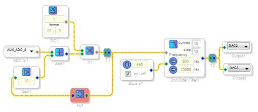
More than likely there's a number of ways to accomplish this, but below is the first one I thought of. The multiplier scales the Aux ADC output from 0 -- 1 (in 5.23 format) to 0 -- 9 LSBs (28.0 format). The feedback adds a bit of hysteresis -- I couldn't tease it into bouncing between steps.
Best regards,
Bob
Hi Bob and Bob:
I believe the Aux ADCs have built in hysteresis. Try it out before adding extra code and let us know how it works. Also, please be careful on the type of potentiometer you use. Linear / Logarithmic. Use Linear if possible but you probably are already doing this.
Regards
Miguel
Thanks for the quick reply
I will give this a try this morning and see how I do.
Is there a way to query a data value on a node in this sort of application?
If so it would make debug much easier.
Bob J.
On Mon, Feb 11, 2013 at 9:45 PM, KJBob <
Hi Bob:
The readback cell allows you to read a value directly from SigmaStudio. It even has a continous readback option (red button) that tells the PC to constantly poll for new values from the node.
Is this what you need?
Regards
Miguel
Thanks for the tips. This is great stuff.
Read back has been some help but seems limited.
Read back works fine with larger numbers (like reading aux_ADC values) but
seems to drop off the bottom 4 bits.
This makes reading the 28 0 format index values of the filter impossible
with read back.
To show the loss of the bottom 4 bits connect a DC source in 28 0 format
and set the value to 16, connect a read back block set to hex format and it
returns 0,0,1 showing the bottom nibble has been dropped. It should have
returned 0,0,1,0.
This means you can not see the generated index values of 0 to 9 with read
back. Oh well it has been very useful with the jubber issue below.
Good news is I now have the filter circuit controlled by the Aux_ADC and my
linear pot. With no feed back there is filter set point judder between
filter curves if the pot is carefully adjusted to find just the right point.
I added your suggested feedback but it did not solve the judder issue and
with a suggested feed back gain of 10 adds only 0.0000019 in 5 19 format, a
very small added voltage and does not over come the pin judder voltage.
At 1/2 POT rotation the Aux_Adc returns 0.50 in 5 19 format with 0.005
judder in value in 5 19 format. This is about 1% and seems high. I have a
100nF bypass right at the ADC pin for noise bypass and reading the pin
voltage right at the ADC pin with 4 1/2 digits of resolution shows NO
variation in the pin voltage, so not sure what is up here.
If in increase the feedback gain to 10,000 I get 0.02 (5 19) of hysteresis
and this provided rock solid filter setting. So we are good in my
application here.
Would like to understand the Aux_ADC judder a bit better. Could the large
Aux_ADC judder be in fact caused by the built in hysteresis poping values
back and forth on pin noise? Can this hysteresis be turned off to see if
this is a issue?
Again thank you for the great support. This is one of the ways AD stands
out in the industry for designers.
Bob
On Tue, Feb 12, 2013 at 9:42 AM, MigCha <
Hi Bob,
The ADAU1701's DSP Readback format is 5.19, rather than 5.23, so yes, the bottom nibble is dropped. You can see the details about that here: http://ez.analog.com/thread/4460
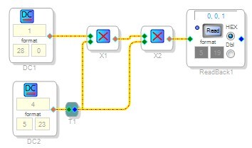
If you want to read back the bottom nibble, you need to bit-shift by 4 bits. This means you need to use two multiply cells, and connect them to a DC value of 4 (in 5.23 format). So, you're multiplying by 4 twice, effectively multiplying by 16, which results in a bit-shift to the left of 4.
Here's a working example:
Luckily, the newer SigmaDSPs (ADAU1761, ADAU144x, etc.) have 5.23 data readback capability, so this isn't an issue.
HI Bob:
Glad to hear you have it under control. I forgot to mention that the reaback on the 2nd generation SigmaDSP is limited to 3 bytes. This was fixed to full word (5.23) in the next generation SigmaDSPs (1761,1781 and 144x). What I do when trying to debug this lower bits is to scale the signal up using a regular gain. You can only scale it up by linear 16 so you might want to use a couple of Gain elements.
Anyway I'll let an apps engineer comment on the hardware ADC hysteresis and how to set up (I don't remember) but is highly likely that in the register window there is a way to control a register that controls this hardware, incluiding it's hysteresis.
Fun stuff.
Miguel
Miguel
I will have a deeper look as I see the exact same 1% judder in mid values
on my EVA board when I read back the POT Aux_ad3 pin.
Both boards not likely to have the exact same noise levels so this is
something else.
Like to reduce it as it limits the number of safe steps I can use.
Bob J.
On Tue, Feb 12, 2013 at 11:54 AM, MigCha <
Please log in to reply.