1701 flip flop
I am trying to make a simple LED flasher using the ADAU1701, and seem to be missing something rather basic.
I used the duty cycle idea found here https://ez.analog.com/message/12324#12324
But, when I try to make the tone generator go less then about 300Hz, it seems to fail (I guess the counter isn't large enough.)
Anyway, I am trying to use two timers with external reset but when I try to feedback the second to the first, I get an "Illegal feedback loop detected" error.
I want the LED to flash at about 50% duty cycle at 1 Hz.
Any Ideas?
Thanks, Mark.
Audio Signal Processors
SigmaDSP Audio Processors
adau1701
Mark,
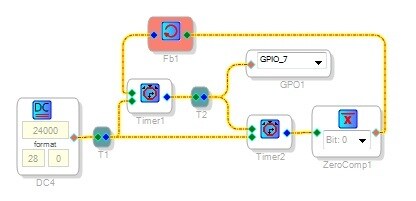
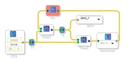
I like your implementation of a master-slave flip-flop with two counter-timers. With a few mods it works fine:
Use the Feedback cell as shown when sending outputs back to previous inputs; this eliminates "illegal feedback" errors.
Set the count threshold DC source to "28.0" format.
Do the Boolean inversion back to the first timer with a Zero Comparator as shown. It turns a zero input into a 1 in any desired bit position, and any nonzero input into a zero output. By contrast the Signal Invert block is an analog inversion (+ to -, 180 degree phase shift, etc.). Its output was never recognized as zero by the following timer.
Take the output between the two timers, where it's a one while the second timer counts up. The second timer's output equals 1 only during the brief instant when the whole thing repeats.
Attached is your circuit with the mods. I assume you're running a custom board, because GPIO7 is wired to the class-D amp enable on the ADAU1701MINZ eval board. I tested the 1 Hz output with a Fluke probing across R1 on that board.
Bob
Hi CoolJavelin
How about simply using a square wave with an offset for making the LED flash?
Miguel
Hi Miguel,
Yep, the square wave with offset uses only 30 instructions, compared to 41 for the timer flip-flop. And it works down to 1 Hz, or even 0.01 Hz.
Bob
OK, sorry about the delay getting back to you, but life does happen.
I am using a custom board, Specifically one from Audera. This board has the 2 audio analog inputs and 6 outputs, plus 90% of the digital lines going to connectors too.
In this way, I can easily connect it to a TI Docking Station and a 28027 ControlCard for testing the 1701.
I must have has something wired wrong because none of the audio sources worked properly, in addition, any sine wave generated was very distorted.
As soon as disconnected it from the TI part, all seems to work well.
I am able to use the first circuit with the AB > CD circuit and a triangle wave and slow the triangle wave to 1 Hz and flash the LED with a GPIO.
All is good, thanks for your help.
Mark.
Miguel:
I am interested in using the "square wave with offset", I understand the square wave source, but don't understand the "offset."
Can you elaborate this and how would I output to the GPIO?
Thanks, Mark.
Hi Mark
A square wave gives you either a -1 or a 1. If you offset this by adding 1 to it, your value will be between 0 and 2. When feeding this result into a GPIO then you will get your blinking LED.
Let me know if this isn't clear.
Miguel
Hi Mark,
Just to be thorough, I want to make sure that you are not planning on driving the LED directly from the GPIO port on the ADAU1701. The ADAU1701 GPIO ports can source/sink a maximum of 2 mA, while most LEDs require more than 10 mA. I would recommend that you use some kind of buffer/driver with a limiting resistor between the GPIO and the LED to source/sink the current.
Best regards,
Coleman
This question has been assumed as answered either offline via email or with a multi-part answer. This question has now been closed out. If you have an inquiry related to this topic please post a new question in the applicable product forum.
Thank you,
EZ Admin
Please log in to reply.