Correlating Voltage on ADC to 5.19 Format
I have a simple application as part of my project to create a window detector so that when an analog voltage is applied to an ADC input, I create a logic level out to control other functions inside the ADAU1701. I've figured out how to make it work with the Tolerance Analyzer, but there is a portion of this that I don't understand. When I apply a voltage of 2.6 VDC to the ADC, and I do a Readback on the DSP core value, it reports 0.61 decimal. I was easily able to multiply this by a factor to get within the range of the Tolerance Analyzer to make this work, but what is the calculation to determine what the Readback value will be for any given input voltage?
After reading several forum posts, and the ADAU1701 datasheet, I see that the full scale range for the ADC is 3.0V. I also undertand that the full scale value for the core is 1. Please also confirm if I'm understanding this correctly.
Any insight would be appreciated, since I'm sure it's something terribly simple I'm missing here.
Audio Signal Processors
SigmaDSP Audio Processors
adau1701
Hi Byron,
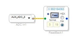
Your understanding of the Auxiliary ADC is correct. It has a full-scale range of approx. 3 volts, which translates to about 1.0 on a Read-back cell connected directly to the ADC block like this:
The above is with 3.0 volts to the ADC, here are some readings at different voltages:
Volts DC Read-back
0.00 0.00039
1.00 0.3376
1.50 0.5093
2.00 0.6850
2.60 0.8926
I measured these by probing across the evaluation board's pot R30, frequently shorting its pins in the process. Sometimes this would necessitate another link-compile-download to restore operation. The funny thing is, after each such reset, the read-back was quite lower than expected, just as you read back 0.61 at 2.6V. Going back to the pot I found that it wasn't where I thought I left it before shorting the pins, but quite a bit lower. Setting the pot correctly resulted in read-backs in the expected range as shown above. I'm wondering if you try your test again, you may find a more accurate result. The Aux ADCs should provide, within their limitations, a read-back of (Vin / 3.0 volts), or Vin = 3.0V x read-back.
Bob

Thanks, Bob. Your explanation is accurate. The aux ADC should have a 3 V range. A more detailed explanation of the 5.19 format is available here: https://ez.analog.com/message/13379#13379
iPhoneから送信
2013/01/10 19:29、"KJBob" <analogvm-admin@analog-vm.hosted.jivesoftware.com<mailto:analogvm-admin@analog-vm.hosted.jivesoftware.com>> のメッセージ:
EngineerZone<https://ez.analog.com/index.jspa>;
Re: Correlating Voltage on ADC to 5.19 Format
created by Robert Blowsky<https://ez.analog.com/people/KJBob>; in SigmaDSP Processors and SigmaStudio Development Tool - View the full discussion<https://ez.analog.com/message/72750#72750>;
Thanks Bob. I appreciate you taking the time to do some measurements. I've repeated the Readback on my project, but re-measured my ADC voltage at 1.81V and not 2.6 like I first thought it was. The Readback value is still 0.60839 which now makes sense if it's simply Vin/3.0V since the math now works out.
Brett, Thanks for pointing out the FAQ (RAQ?) on number formats, they still confuse me and the info there is very useful.
Byron, I'm happy you got the correct results, and thanks for your reply.
Bob
Please log in to reply.