From EVAL-ADAU10701MINIZ to a project...
Hello everybody and happy New Year!
This is my second post. I hope I’m posting in the right place…
A few days a go I purchased an EVAL-ADAU10701MINIZ. I’m new to DSP but I managed to put together a couple projects in SigmaStudio.
My next step is trying to build a circuit board that uses the ADAU1701. The idea is use the evaluation board schematic as a starting point.
There are a few things I am not sure I entirely understand:
1) I measured the frequency response of the EVAL board and I noticed a cut of the high frequencies. Around -1dB at 9 kHz going down as the frequency increases. The out filters are set at around 50 kHz. Is this due to the input filters?
2) The connector J8 indicated a USB_CLK signal coming from the iUSB. I can’t see the signal be used anywhere in the EVAL board schematic. Is it used in some way that I can’t see? Does it have to be connected anywhere?
3) There is something that doesn’t entirely convince me in what I think is the Writeback Trigger (Q2 circuit).
Q2 senses the power supply using DVDD. It kicks in when it senses a drop. However, C15 and C16 sustain DVDD but also the writeback trigger. Q2 cannot sense the power drop as it is “hidden” by the presence of C15/C16. Wouldn’t be the attached circuit more effective? I am not sure but I suspect that as the writeback trigger would be faster, it should be possible to remove C15 or C16 or at least reduce their values. I added C100 but I don’t think it is, strictly speaking, necessary - C45 should be enough.
Audio Signal Processors
SigmaDSP Audio Processors
adau1701
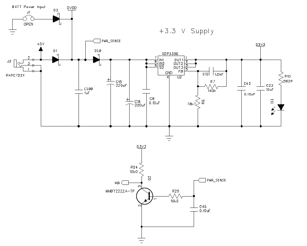
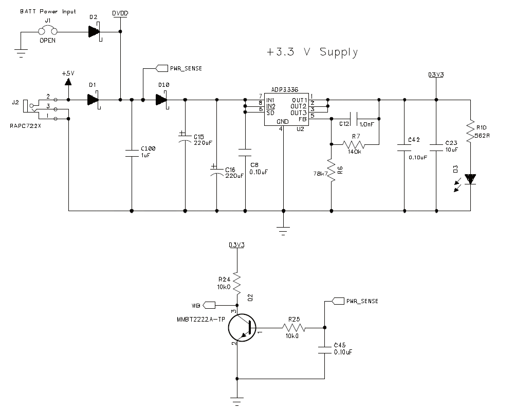
I forgot a question
4) I can't find the output impedance of the VOUT0...VOUT3 pins. Does anybody know the value?
Thanks
3.3V
Happy new year to everybody
Also I have need to know if the signal USB_CLK in the eval, is used, I don't find any reference.
Thanks
I think your modification to the eval board's power-fail detector makes sense, it's sure to give much more write-back time than the original. It's how we would do it where I work, if we were implementing that feature.
Thanks for your comment Bob. I wasn't entirely convinced by the original. You have far more experience then me with the ADAU1701/DSP. I'm glad to hear that I wasn't completely off track with my mod.
EDIT: I just discovered that there is post/answer about this:
https://ez.analog.com/thread/7075
The eval board's DAC2, 3 output filters are actually 56 ohms and 56nF, not 560 and 5.6 as in the schematic (the board's bill of materials has it right, also I checked R11, 12 with an ohmmeter).
I probably have a newer version of the schematic. My version indicates R11=R12=56.2 ohm and C13=C14=56nF.
Thus, each DAC's output impedance must be rather low by virtue of internal feedback as a voltage-output DAC, in a small-signal sense.
This is what I thought but is it possible that the high frequency cut is due to a not-so-low out impedance that interacts with C13/C14 ?
ez.analog.com/.../1258.093da83004b784c615d7255fb359b9a5.html
When you lay out your PCB, ADI suggests not using the evaluation board as a guide. Instead, use the guidelines here: https://ez.analog.com/docs/DOC-1889
I saved the link to this page a while ago. Very interesting. Thanks for reminding me about it.
Message was edited by: 3.3V
I did a quick calculation about the high-frequency roll-off. My guess is that an output impedance of around 170 ohm combined with R11/12 and the 56nF capacitors would explain the curve I measured.
I look forward to hearing from AD about the actual value of the output impedance. I'm a little bit surprised it isn't in the datasheet.
3.3V
Hi 3.3V,
I think your modification to the eval board's power-fail detector makes sense, it's sure to give much more write-back time than the original. It's how we would do it where I work, if we were implementing that feature.
The eval board's DAC2, 3 output filters are actually 56 ohms and 56nF, not 560 and 5.6 as in the schematic (the board's bill of materials has it right, also I checked R11, 12 with an ohmmeter). Thus, each DAC's output impedance must be rather low by virtue of internal feedback as a voltage-output DAC, in a small-signal sense. You can plug stereo headphones directly into the DAC 2, 3 output jack and hear a reasonable level. This of course does not speak to the ultimate current or dissipation capability of these outputs.
When you lay out your PCB, ADI suggests not using the evaluation board as a guide. Instead, use the guidelines here: https://ez.analog.com/docs/DOC-1889
I'm not sure why you're seeing a roll-off above 9KHz.
Best regards,
Bob
Hi 3.3V and piero,
The USB_CLK (pin 2 of the 10-way header) is driven from the CLKOUT pin of the Cypress uC. In the original design phase of the USB interface, we had planned for use of this clock port to drive the target board with the 24 MHz USB clock and use fractional PLL settings in various parts to achieve the audio sample rates. Unfortunately, this feature was never implemented in the Cypress firmware or in the SigmaStudio interface.
Best regards,
Coleman
This question has been assumed as answered either offline via email or with a multi-part answer. This question has now been closed out. If you have an inquiry related to this topic please post a new question in the applicable product forum.
Thank you,
EZ Admin
Please log in to reply.