ADAU1701: ADC_RES value, Synchronous Multiplexer
I am working with the ADAU1701 eval kit and have to say this is a truly great product!
Two questions:
- the datasheet describes how to change ADC0/1 resistor values to alter input sensitivity, but is it possible in the same way to increase ADC_RES? I saw some discussion in this thread:
https://ez.analog.com/message/32305#32305
about why lowering ADC_RES was a bad idea, but I wonder about increasing it to make the inputs more sensitive and I don't want to alter the eval board to find out! No big deal if that doesn't work, but it will save me a few parts in my design. Would that compromise signal to noise though?
- I was so sad that ADAU1701 did not have a supplied reverb that I wrote one, but obviously with limited resources I did a mono reverb with a 'stereoized' output, and the initial delay is short. SigmaStudio v3.7.7 I see has an undocumented 'synchronous multiplexer' that doesn't have a demux companion; I wonder if that could be a method of implementing a downsampled reverb? I am perfectly happy with reverb with 5kHz bandwidth, so if any such feature could be supported in a future release I would be grateful since my design does not have the physical space for a larger chip!
Regards,
Jon
Audio Signal Processors
reverb
SigmaDSP Audio Processors
downsampling
adau1701
I am very new to DSP/SigmaDSP (first post) but my understanding is that ADC_RES should be set based on the "core frequency" - for 48kHz and 96kHz is the same.
The input resistors control the input gain. They are similar to input resistors of an opamp used in inverting configuration.
If I'm not wrong, Vin RMS max should be:
Vin_MAX = ((Rin + 2k) / (2k+ADC_REC) * 2V
in other words, to determine Rin:
Rin = ((Vin_MAX/2) * (2k+ADC_REC)) – 2k
You also have to consider that the input impedance changes with Rin.
Zin (above cut-off frequency) = Rin + 2k
This has an impact on the low frequency cut-off:
f = 1 / (2π Zin C)
where C is the value of the input decoupling capacitor.
It's a tricky one... Moreover, I think the two input resistors should be as close as possibe to the ADAU1701 to limit the noise.
Yes, that is the standard method described in the datasheet. However, my application requires switching operating levels, and it will be simpler to switch a single resistor (ADC_RES) rather than two resistors (ADC0, ADC1) that are in the signal path and would thus require an input capacitor sized for the smaller resistor value.
Thinking about this the past couple of days I have to believe the ADC_RES switching idea is not going to work; given that input current noise is fixed, referencing less current as full scale has to decrease SNR, making it the same as a (much easier) digital gain change. Oh well . . . but maybe somehow I am not correct.
Still, I'd love my secound request for downsampling! Lots of potential for that I think
Hi Jon,
Yes, downsampling! Where I work, one of our applications handles telephone-quality audio and does some DTMF tone decoding, where a 8-12KHz sample rate would be ideal. The product also handles full bandwidth audio, so it would be awesome to have both sample rates going in one processor. We have this thing working as-is, but its -1701's instruction space is nearly filled up.
As you noted, your wonderfully simple idea for changing ADC gain may still work well, at least over some limited range. It would still be interesting for someone from ADI to weigh in on this after their break.
Bob
Given the architecture of the chip I don't think savings in instruction set is possible (although I feel your pain there too), but what I need is longer delays. A synchronized mux/demux could be used to interleave a downsampled stereo signal to a single delay line. With four inputs, the interleaved output signal feeds back into the bottom two inputs for an effective 4x increase in delay, right about what I'd need for a reasonable quality reverb.
jon71, as you realized earlier in one of your posts, it's not a good idea to change the ADC_RES resistor to something other than the recommended value, as this would have a negative effect on the noise of the system.
Regarding downsampling for the purpose of reverb... unfortunately it is a bit difficult to do this due to the graphical nature of the design tool. It's only really possible when you have direct access to coding the DSP on the assembly level. However, we are experimenting right now with a kind of downsampled reverb cell that might make its way into SigmaStudio eventually, depending on the quality of the finished product. I'm not sure if it will be small enough to fit in the ADAU1701 or if it will require a bigger SigmaDSP with a bit more horsepower.
Brett, thanks for that answer. Can you comment on the function of the synchronous multiplexer, or whether a demux is possible?
Hi Jon,
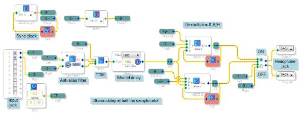
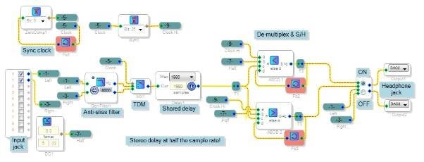
It appears possible to do something like the "synchronous multiplexer" you described above. In the diagram below, the delay alternates between left and right channels, serving both at half the system sample rate. The inverter with feedback chases its tail, producing a square wave at fs/2. This clocks a non-slew mux, alternating channels into the delay. On the output side one could use a standard de-mux followed by a low-pass reconstruction filter, but below I did alternating sample-holds instead:
It actually sounds pretty good despite the lower bandwidth. I didn't try routing one channel through the other to make a double-length delay, but that should work as well.
Best regards,
Bob
Brilliant! Now, off to see if I can afford the instructions . . .
Please log in to reply.