ADAU1701 AUDIO ADC's Problem
I have created a PCB with 2 ADAU1701's. Both are running as slaves. MCLKI is 24.576Mhz . I will not be using any pin as a serial Audio line. So I have no external BCLK or LRCLK to/from either device. All of my audio will be coming from or into the audio DAC's/ADC's. Just for a test, DSP B is feeding an internally generated differential audio signal out of DAC0 and DAC1 (see attached project file). This audio is sent to a differential amp network, added together and output as a single ended audio signal (see image of final signal measured at input of blocking capacitor into ADC1) . The signal ended audio signal is used as an input back into the audio ADC1of DSP B. The ADC_RES is 17.8k ohm, I have 47uF blocking capacitors inline with 18.2kohm resistors into ADC0 and ADC1. I am feeding the input of ADC1 directly to the DAC3 output (see image of output signal measured before active filter). As you can see the sine wave is clipping and nothing I do will prevent this. I have tried changing the gain but Iose one half of the sine wave (see attached image). I'm sure it's something simple I'm missing but can't figure it out for the life of me. Any help would be appreciated. Do i have to have an external LRCLK and BCLK to run the audio ADC's. What could it be?
Audio Signal Processors
SigmaDSP Audio Processors
adau1701
Hi Bill,
The 1701's audio ADCs are internally clocked, thus they don't need LRCLK or BCLK. Judging by your -28 dB scope photo, there's about 40dB too much gain somewhere (the waveform shows much less than half a sine wave, perhaps only the bottom 20%). Perhaps comparing your board's connections at the affected -1701 pin-for-pin with ADI's reference design (from the evaluation board schematic, etc.) might turn up something.
Bob
I will do that and feedback. Thanks for the reply.
It appears that one of the filter capacitors was not soldered down properly. After going through the schematic on the demo board and reheating each component on my board it began to work.
Hi Bill,
I'm glad you were able to troubleshoot your prototype and get it working. Now on to the fun stuff.
Bob
Hello guys, KJBob
We have created a prototype PCB by imitating EVALADAU1701MINIZ design. The problem is, when i use readback function on sigmastudio, ADAU1701 seems not reading any data from adc0 and adc1 pins.
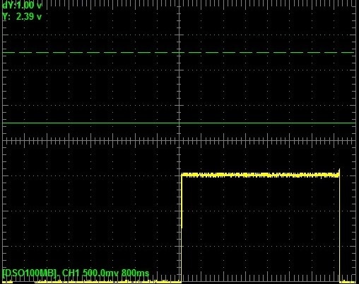
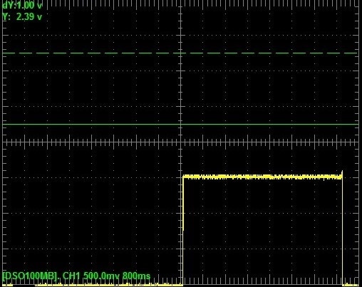
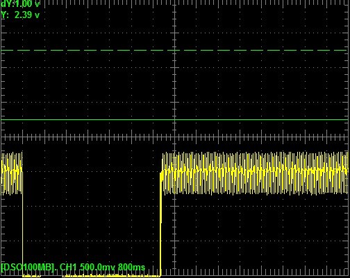
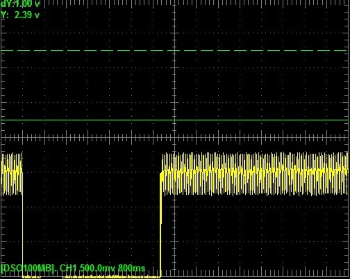
First shot below is the original EVALADAU1701MINIZ signal at pin adc0 and adc1, with a smooth ripples at 1.5V. Whereas the second shot is from our prototype board signal at pin adc0 and adc1, with a great ripples at 1.5V.
Is the ripples caused the problem?
FYI, I can download sigmastudio schematic to the prototype board using USBi successfully and tested readback function for I2C control. I also have tried to reheat of each component regarding adc0 and adc1 input pins but the problem won't solve.
Any suggestion or idea on how should i proceed my work?
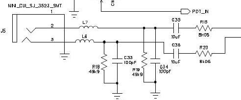
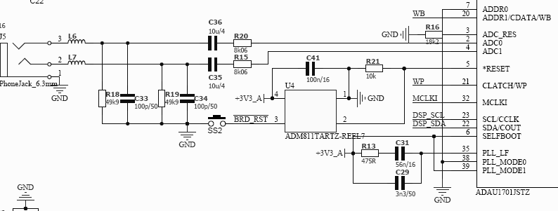
And could anybody please confirm which one is the right value of resistance of R15 and R20? we were used 8.06kΩ,
but schematic of evaladau1701miniz, datasheet pg 8 mentioned 8.06kΩ
on the other hand, bill of material at datasheet page 11 mentioned 8.06Ω but somehow part number refer to 8.06kΩ
Thanks and Best Regards.
Kal


Thanks Bob for the response and explanation.
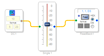
Currently, I can read the ADAU1701 using I2C control as schematic below.
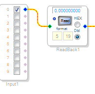
But, could you suggest your insight on what is actually goes wrong with the prototype board as I can only get value of zero all the time at ADC pins (measure by readback function as shown in schematic below).
Also by using readback function, the original board gave us fluctuate numbers which are the result that I want to achieve.
I am suspecting the problem comes from our circuit of ADC as shown below. But, right now I am not be able to nail down in what aspect it goes wrong.
If anyone has an idea or suggestion to share for solving these problem would be much appreciated.
Thanks and Best Regards,
KaL
Hello Kai,
The eval board's schematic is correct (8.06K ohms). The ADAU1701's ADCs respond to input current at 100uA full-scale. Thus the 8.06K resistor (along with the ADCs' 2K built-in resistance) sets their full-scale input voltage at 1 volt peak (2V p-p, or about 0.7V RMS). For more info, please see page 21 of the ADAU1701 data sheet.
Since the ADCs are current-sensing, very little ripple voltage would normally be seen there, even with a full-scale audio input.
Best regards,
Bob
Please log in to reply.