Delay measurement
Dear friends, I am developing a tool with the ADAU1701 and I need to measure the delay between acoustic alert boxes from a microphone, anybody have any idea how I can make these measurements? I read some documents which speak of crosscorrelation and fft
Audio Signal Processors
SigmaDSP Audio Processors
adau1701
Hi Soundmax:
What's your excitation signal for measuring the delay? What type of signals do Acoustic Alert Boxes generate?
Crosscorrelation would do the trick. Unfortunately, the SigmaDSP (at least the first 2 generation cores) can't do an FFT.
Miguel
Miguel,
I can use any signal, a sinusoid, a pink noise, a sequence ... since I could measure the delay so I can align the delay between channels.
Thank you,
Cleber
any Help ????
Hi Cleber:
I think the SigmaDSP is capable of doing this. There are many ways of doing this. In the past we experimented with Zero Crossing of Sine Sweeps and Counters. The once concern is that I'm not sure of an exact combination of existing blocks that could do this. The other option would be to do a runtime cross correlation of a signal that is generated at store at runtime. This needs to be coded specifically for your applications.
Let me know if this makes sense.
Miguel
Miguel,
I believe that the system of zero crossing is very sensitive to working with a microphone ...
My product must discover the difference in phase between various components that adjust the processor correctly, understand?
thank you
Cleber
Hi Cleber,
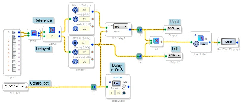
You can try cross-correlation with a setup like that shown below. The circuit uses two inputs, a non-delayed reference signal and the signal whose delay is to be measured. It delays the reference and then multiplies both signals together. This is the basis of cross-correlation, except that the official definition involves integrating the multiplied result over all time. That being rather inconvenient, I settled for a low-pass filter (as is often done with RMS-DC conversion, etc).
Apply your reference signal to ADC0 and your delayed signal to ADC1. Starting from zero, advance your eval board's control pot until you find a maximum positive reading on the Real-Time Display. Once that chore is done, the ReadBack cell provides the delay measurement.
With the delay set for 960 samples max, one would expect full-scale at 960/48000 = 20mS. However, testing with an identical 200Hz sine wave at both inputs shows a maximum at zero delay (as expected), and another one when the read-back cell shows 0.5. Since the 200Hz sine wave starts over at a period of 5mS, the dialed-in delay must also be 5mS. So the thing calibrates to: delay in mS = (read-back) x 10.
Note that when using a repetitive waveform for your delay measurements, the first peak is the valid one -- additional ones are from 360-degree cycle repetition. It may prove difficult to automate this measurement since your algorithm would need to converge on a maximum. This is hard for a machine to do but easy for us (it's like focusing a camera; you rock the lens back and forth till it's clear). A microcontroller tied to your -1701 with some smart programming may do the trick.
Best regards,
Bob
This question has been assumed as answered either offline via email or with a multi-part answer. This question has now been closed out. If you have an inquiry related to this topic please post a new question in the applicable product forum.
Thank you,
EZ Admin
Please log in to reply.