ADAU1701 won't self-boot
Hi all,
I recently built a circuit using the ADAU1701 in selfboot mode, which is basically the circuit found on page 3 of AN-923, with the WB trigger tied to GND (no WB required) and RESET being connected to a power-on reset supervisor IC. Components in the PLL filter circuit differ slighty from the suggested values, the resistor is a 470 ohms and the suggested 56n capacitor consists of 33n+22n in parallel, because those were the values I had on hand.
I am using both ADC inputs, 2 DAC outputs and a couple of GPIOs to connect incoming I2S data, a D/A selector switch and to control LEDs and a relay. To burn the EEPROM (24AA256, 32kByte) I use the generated E2Prom.hex file and an EEPROM programmer + software (PonyProg). Programming of the EEPROM itself works fine, no issues.
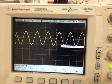
When I first powered the circuit (EEPROM installed), I noticed that the GPIOs were not behaving as they should (the 'high' or 'low' states i found had nothing to do with the program, one of the was putting out 1.2V?!) and that no signal was put through to the DACs. I suspected the oscillator not to work properly (the crystal has a CL of 10pF and 22pF capacitors going to GND), but I have a nice 12.xxxMHz sine on the MCLKI pin.
Next thing I did was to check my schematics and found that the +3V3 connection to IOVDD was missing on my PCB! So after soldering a small wire from +3V3 to IOVDD and its decoupling capacitors I repowered the circuit, but found the same problems as described before. I programmed the EEPROM with a small test program using no GPIOs (all configured as debounced inputs), that should output a 1kHz sine to DAC0. No change. GPIOs still behave as described earlier and no signal on DAC0. Manually resetting the device shows no effect.
It seems that the program is not loaded from the EEPROM, as things turn out the same even with no EEPROM installed.
I read the voltages as follows (referred to GND):
- IOVDD, PVDD, AVDD: +3.26V
- DVDD: +1.75V
- CM: +1.52V
- FILTD: +1.64V
- FILTA: +1.62V
- ADCs and DACs are properly biased to 1.5V
Is it possible that the missing +3V3 connection to IOVDD caused damage to the ADAU1701?
EDIT: It seems that the GPIOs are permanently configured as inputs, since their 15k pull-up resistors allow enough current to flow into my NPN transistor buffers to turn the relay on, for example. I guess that's why I was measuring 1.2V on the GPIO driving the relay.
Best regards,
Roman
Audio Signal Processors
SigmaDSP Audio Processors
adau1701
Hello Roman,
The -1701 data sheet pg. 10, 12 does put a 0.3 volt limit on digital I/O going above IOVDD. In theory the chip could have been damaged if I/O line(s) went high while IOVDD remained unpowered. However, experience suggests that only an active high driving input with current behind it could cause such damage; resistor pullups excepted.
Have you looked at your SDA and SCL lines at start-up? This would show if the -1701 is trying to read your E2Prom.
Best regards,
Bob
Hello Bob,
Thanks for the quick response.
I have attached my measurements. The sine wave is measured on the MCLKI pin of the ADAU1701:
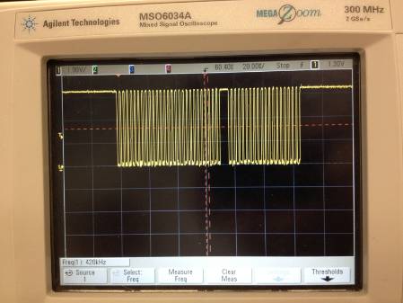
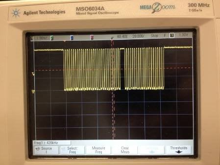
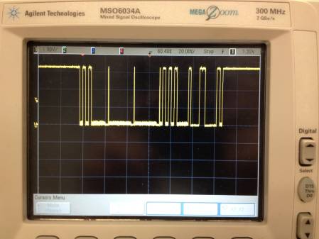
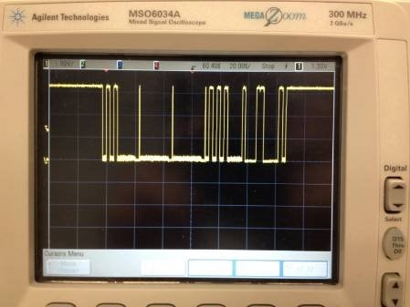
There is definitely activity on the I2C lines. The following signals appear on SCL/SDA shortly after the ADAU exits reset. The DSP should be "alive" and in self-boot mode if it outputs clock and data on the I2C, correct?
SCL:
SDA:
The SCL/CLK signals were measured directly on the corresponding EEPROM pins. WP is pulled up to +3.3V via a 2.2k resistor.
I use the E2Prom.hex file located in the "IC2" folder of my Sigma Studio project, load it into PonyProg and use the SI-Prog adapter to program the EEPROM (using the "24256" device setting). The device is written successfully and the contents are veryfied properly.
For the moment, I have no clue what's going wrong. I can post schematics if this is of any help.
Best regards,
Roman

Hi Roman,
Have you tried using SigmaStudio to download directly to the EEPROM? The step-by-step instructions are listed on this thread under "Method 1". https://ez.analog.com/message/5759#5759
Hello Brett, Hello Bob,
The problem is solved!
I was using the wrong HEX format to burn my EEPROM. I first had to convert the E2Prom.hex file to 16-bit Intel Hex, then transfer the data into my serial EEPROM using PonyProg. I found the final answer in this thread.
The DSP works fine now, GPIO logic included.
It would be nice to have Sigma Studio exporting the EEPROM hexfile in Intel Hex, as already stated elsewhere.
Thanks to both of you for your time and efforts.
Best regards,
Roman
Thanks for letting us know the outcome, Roman. It certainly would be nice to have intel hex as an output option. That's currently on our wishlist!
Please log in to reply.