EVAL-ADAU1442EBZ Op Amp circuits
I am following the schematics provided in the UG-032 datasheet for the eval-adau1442ebz to create our own board using the adau1442 (we also bought an eval-adau1442ebz for testing). My question is on the audio outputs (page 30 of 44, Figure 53) there is a 3.3nF capacitor and 49.9k resistor in parallel with each other on the op amp output right before the jack. My application is going to be connected to a 600 Ohm impedance system (telephone system) and from everything I have read so far about impedance matching I can't figure out why that capacitor and resistor are there. I had hopes someone could explain a little bit more about their function and if I need it for my system or not (I've read that for typical audio applications you want to avoid impedance matching because it degrades the integrity of the signal, but in the telephone world impedance matching is a must).
Thanks in advance for any help!
Audio Signal Processors
impedance_matching
eval-adau1442ebz
adau1442
SigmaDSP Audio Processors
telephone
Show More
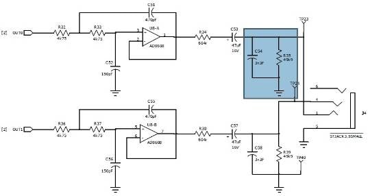
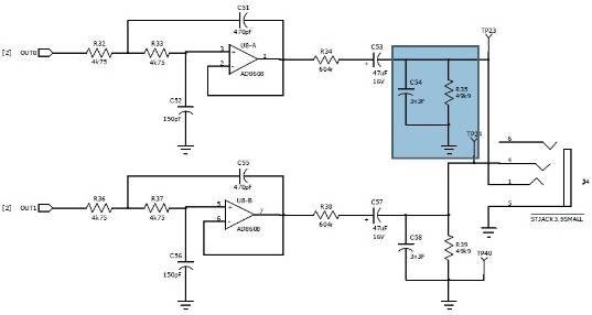
I included a screenshot of this part of the schematic, with the components in question highlighted.
(click the picture to enlarge)
The purpose of these components is to provide a ground reference for the signal pins on the jack. This means that when no plug is inserted into the jack, the line will naturally rest at around 0 V respective to ground on the board.
If these components were not present, then the signal lines from the jack would connect directly to the 47 uF AC-coupling capacitor. In the event that a plug is not connected to the jack, then the signal lines would be floating. The problem with floating lines is that the voltage can "wander", and when a plug is eventually connected to the jack, there will be a quick step in the voltage since the potential of the jack may be different than the plug. This can make a pop or click noise.
So, in effect, these components are for pop/click prevention.
By the way, the very large size of the resistor means that it only provides a "weak" pull-down to ground, and it should not have an effect on the audio signal because its impedance is several orders of magnitude higher than the signal line.
Ah that makes a lot of sense! As far as the impedance goes, the 604 ohm resistor acts as my source termination right? So does that mean on the receiving end (which is the same as the audio input circuit thats on the eval-1442ebz) I need to add a 604 ohm resistor from the input line to ground? Won't the 604 ohm and the (receiving end) 49.9k ohm in parallel affect the impedance (so the line equpiment would see it as an impedance of 596 ohms)?
Thanks again!
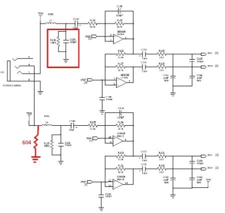
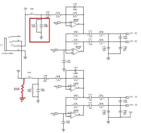
Yes, the effective source termination will change by a few ohms, so you should take that into account if you want exact impedance matching... And if you're already going that far, it would make sense to calculate the impedance of the trace as well and take it into account.
Please log in to reply.