Something about SigmaStudio clipper, probe and others
Good morning,
i'm using an adau1701 evaluation kit from few days and i'm really impressed for its capabilities.
I got the kit three days ago and, starting from zero, i almost completed my job. Really nice!!
But, during development, i had some little "troubles" which i report:
The probe frequency axis cannot be set above 22KHz, while i'm using 192KHz sampling rate.
Regarding the clipper, i cannot get the hard clipper to work properly: i need a symmetrical
clipper, so i have to clip equally both the positive and negative level.
Well, i select to clip both edges, i put the two constants, the program which is running
on the 1701 is not updated when i change the clipper parameters, so i compile and download and
it seems that it always clips just one part of the wave or, even if i put identical
coefficients, eg. 0.5 and -0.5, it does an asymmetrical clip; the cubic clipper is ok but i cannot use it.
Using the dynamic compressor, is there a way to implement a "gating" function ?
In detail, i should freeze the release or setting it to a large value so
the gain should not rise if the input signal falls below a certain threshold, this to
avoid amplifying noise.
Then, sometimes i cannot edit the parameters into the elements: i can select and drag them,
but if i try to change something, the edit box doesn't allow writing and the pointer changes to
the "wiring" icon, but all ports are still connected.
I have to close the project, not the ide, and reload it again.
Last question, i'm using a fir filter "grew" to have two inputs and two outputs.
I was expecting to have just one coefficient table and two separated memory blocks
for the datas.
Instead, it seems that it has also two separated memory blocks for the coefficients
though they are identical.
I don't know if this would be possible, but if the "grown" filter could be implemented
using just one coefficients table and separated data buffers, there could be more
space in memory.
Many thanks for your support.
Audio Signal Processors
processors and dsp
SigmaDSP Audio Processors
Processors and Microcontrollers
adau1701
The probe frequency axis cannot be set above 22KHz, while i'm using 192KHz sampling rate.
I will request that this limit is increased in future releases.
Regarding the clipper, i cannot get the hard clipper to work properly: i need a symmetrical
clipper, so i have to clip equally both the positive and negative level.
Well, i select to clip both edges, i put the two constants, the program which is running
on the 1701 is not updated when i change the clipper parameters, so i compile and download and
it seems that it always clips just one part of the wave or, even if i put identical
coefficients, eg. 0.5 and -0.5, it does an asymmetrical clip; the cubic clipper is ok but i cannot use it.
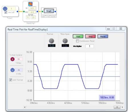
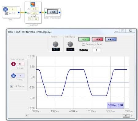
I do not see this problem. I tried the hard clipper on the ADAU1701 today and saw proper operation, with clipping at the desired points. Please see the screenshot attached.
Using the dynamic compressor, is there a way to implement a "gating" function ?
In detail, i should freeze the release or setting it to a large value so
the gain should not rise if the input signal falls below a certain threshold, this to
avoid amplifying noise.
Please see this thread: Creating a noise gate in SigmaStudio
Then, sometimes i cannot edit the parameters into the elements: i can select and drag them,
but if i try to change something, the edit box doesn't allow writing and the pointer changes to
the "wiring" icon, but all ports are still connected.
I have to close the project, not the ide, and reload it again.
I think you are probably experiencing this problem: FAQ: Why can't I control any of the knobs or sliders in my SigmaStudio project?
Last question, i'm using a fir filter "grew" to have two inputs and two outputs.
I was expecting to have just one coefficient table and two separated memory blocks
for the datas.
Instead, it seems that it has also two separated memory blocks for the coefficients
though they are identical.
I don't know if this would be possible, but if the "grown" filter could be implemented
using just one coefficients table and separated data buffers, there could be more
space in memory.
I agree. The reason for this problem is that this particular cell seems to have an "add" function (which duplicates the program, parameters, and data), as opposed to a "grow" function (which duplicates the program and data, but not the parameters). I will report this.
Many thanks Brett,
i made other tests now on the clipper and i discovered this:
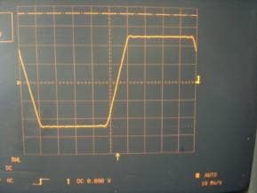
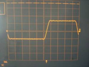
this is a live sinusoid input on a single input hard clipper:
it is ok and symmetrical like your graph and it's
how it should work.
Now i grow the clipper to have a second input and,
without touching the clipping levels, the oscilloscope Y
axis sensitivity and the generator output level,
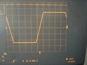
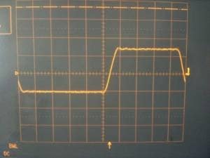
this is what i get:
You can see that both clipping thresholds are lower
(in the upper image you have 5 vertical divisions peak
to peak, in this you have about 2.3 divisions peak to peak)
and the negative part of the sinusoid is clipped more than
the positive.
It seems that the problem arises when you grow the clipper;
with just one input, i confirm, it's ok like you said.
Found the problem:
when growing the clipper, it seems that, while it mantains
just one positive threshold, creates N references for the negative
and intializes them to zero.
Param Address: 3
Param Name: HardClipAlg1up_2 3
Param Data:
0x00, 0x40, 0x00, 0x00
Data 5.32:
0.5
Data 28.0:
4194304
Param Address: 4
Param Name: HardClipAlg1_2 4
Param Data:
0x0F, 0xC0, 0x00, 0x00
Data 5.32:
-0.5
Data 28.0:
-8388608
Param Address: 5
Param Name: HardClipAlg1_2 5
Param Data:
0x00, 0x00, 0x00, 0x00
Data 5.32:
0 <===this is zero while should be -0.5
Data 28.0:
0
One note about the generated header files,
i tried to upload via the host microcontroller the program.
It's all ok, but i noticed that when i read back
the parameter registers, while the program
loaded, for example, this sequence:
...
0xFF, 0xFF, 0x9E, 0x17,
0xFF, 0xFF, 0x92, 0xD1,
0xFF, 0xFF, 0xAC, 0x36,
...
i read back
...
0x0F, 0xFF, 0x9E,0x17
0x0F, 0xFF, 0x92, 0xD1,
0x0F, 0xFF, 0xAC, 0x36,
...
ok, these are 28 bits values packed into 32 bits
so the last nibble should be not important,
but i think that i should read back what i write.
Regarding the gating, my question was different.
Ok, you can avoid noise rushing in with a noise gate, but
what i was asking for was a method to avoid the
compressor's band to release when the input signal
was below a certain level.
It could be intended like a "dual release compressor"
in which one release time, say "fast", is used for
normal operation and another release time, say "very slow",
is used when the input signal is below threshold.
This, in some part, prevents distortion when passing
from silence, where, without this function, the compressors
were totally "open"=maximum gain, to sudden music or
speech: in the first milliseconds, the compressors
have to pass from highest gain to, maybe, the gain that
they had just before the silence part.
In this case, freezing their release or making it extremely
slow when silence begins, results in more pleasant
listening.
Thank you!
Thanks for the great debugging work! This definitely looks like a SigmaStudio issue. I will report it to the software team immediately.
Regarding the top nibble of the data stored in memory... Here's a post I wrote to explain that:
Parameter RAM: Writing 0xFF but Reading 0x0F
Regarding the compressor, I think there is a method we can use to implement the functionality you want. I would recommend using two envelope followers (one fast and one slow) and then using a logic cell to select between them. That would feed into the detection input on a dynamics processor. This would require some refinement, but I imagine it could work.
Hi, from my own experiments with ADAU1701 and Sigma Studio V3.10 Build 4 Rev 1326
the problem found by drugoimir is still present with this release.
I'm using a custom library written for arduino/energia to talk with DSP and to fix this problem I have to write
also the "ghost" parameter wich is a duplicated parameter negative threshold.
I'm using an hard clipper block growed to stereo, I see
Param Address: 4
Param Name: HardClipAlg1up_3 4
Param Data:
0x00, 0x80, 0x00, 0x00
Data 5.32:
1
Data 28.0:
8388608
Param Address: 5
Param Name: HardClipAlg1_3 5
Param Data:
0x0F, 0x80, 0x00, 0x00
Data 5.32:
-1
Data 28.0:
-16777216
Param Address: 6
Param Name: HardClipAlg1_3 6
Param Data:
0x00, 0x00, 0x00, 0x00
Data 5.32:
0
Data 28.0:
0
but the last one is the second negative threshold parameter wich is wrongly initialized to zero, it should be
-1 to work properly (symmetric clip).
Also I noticed sigma studio generated header files are missing this parameter address
...
...
...
/* Module HardClip1 - Standard Clip*/
#define MOD_HARDCLIP1_COUNT 2
#define MOD_HARDCLIP1_DEVICE "IC1"
#define MOD_HARDCLIP1_ALG0_HARDCLIPALG1UP0_ADDR 4
#define MOD_HARDCLIP1_ALG0_HARDCLIPALG1UP0_FIXPT 0x00800000
#define MOD_HARDCLIP1_ALG0_HARDCLIPALG1UP0_VALUE SIGMASTUDIOTYPE_FIXPOINT_CONVERT(1)
#define MOD_HARDCLIP1_ALG0_HARDCLIPALG1UP0_TYPE SIGMASTUDIOTYPE_FIXPOINT
#define MOD_HARDCLIP1_ALG0_HARDCLIPALG1UP1_ADDR 5
#define MOD_HARDCLIP1_ALG0_HARDCLIPALG1UP1_FIXPT 0xFF800000
#define MOD_HARDCLIP1_ALG0_HARDCLIPALG1UP1_VALUE SIGMASTUDIOTYPE_FIXPOINT_CONVERT(-1)
#define MOD_HARDCLIP1_ALG0_HARDCLIPALG1UP1_TYPE SIGMASTUDIOTYPE_FIXPOINT
/* Module Nx2-1 - Stereo Switch Nx2*/
#define MOD_NX2_1_COUNT 3
#define MOD_NX2_1_DEVICE "IC1"
#define MOD_NX2_1_ALG0_STAGE0_STEREOSWITCHNOSLEW_ADDR 7
...
...
...
So I have modified my libraries to write to this "ghost" parameter and now it seems to work ok.
Thanks
Please log in to reply.