1701 Oscillator start problem
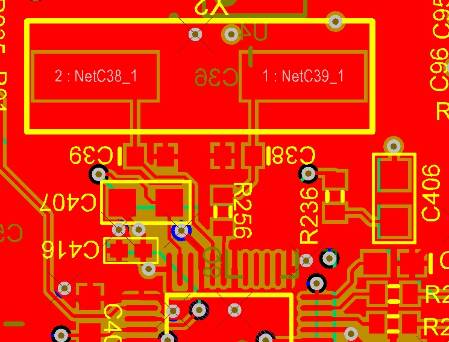
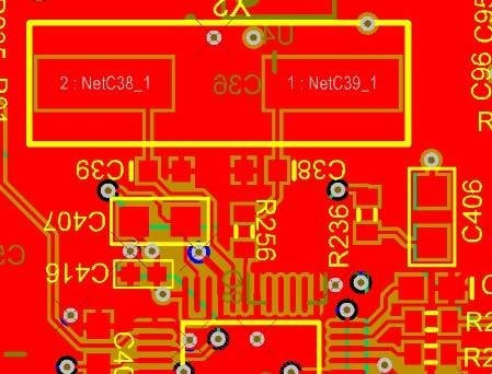
We are using 7 ADAU 1701's on the same board. One is the master with a 12.288 MHz clock and is programmed to send a 3.07 Mhz clock to the other 6 via MP11. The master DSP oscillator has had a history of not starting reliably over several hundred PCA's. Some boards are OK, some are not. Several modifications have been tried, including changing the layout to one you see here:
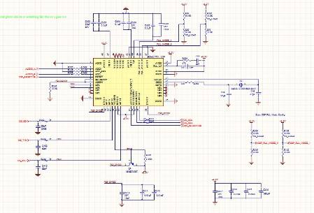
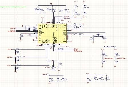
C38 and C39 are 22 PF, 27 PF has been tried. The crystal has been changed to a different manufacturer with no effect. The resistor R256 is 100 ohms. If the crystal is tapped it will start. Changing R256 to 0 ohms will result in reliable starting. Bypassing is extensive with a 10 UF ceramic cap and 2 .01UF caps on both 1.8v and 3.3V close to the DSP. C416 is a 680PF cap bypass. This is the schematic of this section of the board:
There is a ground layer under the top copper shown in red. The PLL line runs under the traces to the crystal on the signal layer under the ground layer.
Any thoughts would be very much appreciated.
G Cook
I think I've found the problem. We use a switching 3.3V regulator, and it generates about 20Vpp of ripple at approximately 600KHz. If I power the DSP from a bench supply, the oscillator starts reliably. This would explain the resistance of the problem to layout and part value changes. I am pursuing that line of thought and will report when the problem is resolved.
I cannot verify that a cleaner +3.3V supply fixes the problem. I reduced the ripple to less than 2-3 mV and the oscillator still is not starting consistently.
Hi GCook,
I think the supply could very well be the cause of the issue. The PLL design relies heavily on the operation of a VCO - voltage controlled oscillator. That VCO is referenced to the PVDD supply pin on the chip. A change in voltage will shift the frequency of the VCO, causing the PLL to go out of stability briefly, but the PLL will then correct itself and lock at the new frequency. However, if the change on the PVDD supply is periodic - which would be the case with a switching supply - the PLL will be shifting in frequency quickly enough that it will not be able to maintain lock.
All of our evaluation boards use linear regulators, so I haven't been able to test with a switching supply before. Maybe if you placed some large capacitors on the output of the switching supply, that would further reduce the ripple and relieve the problem.
Thanks, Brett. I appreciate your comments.
Is it possible that the +3.3V rise time is an issue? I believe that I have identified very subtle differences in the rise time of the 3.3V and the way the oscillator subsequently behaves.
I have done experiments where the rise time on the supply has been quite long, but no real negative effects were noticed. Same thing with fast rise times. I think the key is stability.
In purely analog solutions, you have a really direct tie between the supply and the circuit behavior from ground all the way up to supply. However, our PLL circuit is a kind of digitally-controlled-analog, which means the oscillator will be completely shut down until a certain threshold is reached that will allow the digital circuitry to come to life. So, I think at that point the PLL will simply be unstable until the supply has reached its nominal value, but there's no real threat of locking up, etc., based on rise time.
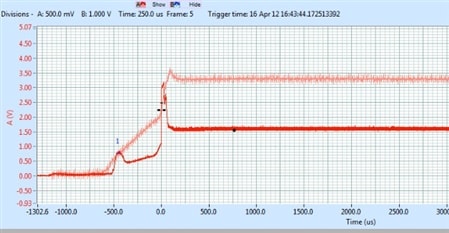
I have used an external bench supply and agree that the PS rise time can't be too slow. However, It looks like with a particular rise time the oscillator has too little gain to sustain oscillations. This is the way the power supply (light red) and the output side of the crystal look when it won't sustain oscillations:
T
Sometimes it will start after 500 to 1000 uS, sometimes never.
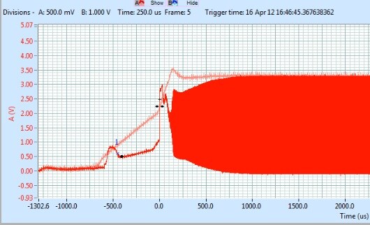
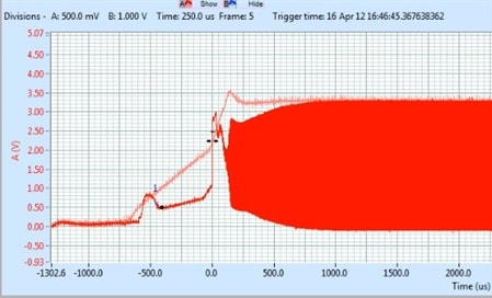
And this is the way it looks with additional capacitance on the power supply to slow the rise time by approximately 100 to 200 uS:
This behavior is consistent across several samples so far. Adding a cap to the PS line always fixes it.
I don't have a programmable supply to test this theory more thoroughly, unfortunately.

Out of curiosity, are you using the exact passive component values shown in Figure 15 of the datasheet? http://www.analog.com/static/imported-files/data_sheets/ADAU1401A.pdf
We are using the recommended values, actually there is more bypassing than shown on the data sheet schematics. I've tried more and less bypassing without any affect on this issue.
I think after further investigation that the issue is a very narrow range of 2V to 3.3V rise times that may cause an internal latch type of problem (perhaps in the PLL?), which has the effect of loading down the output of the oscillator stage. The power supply has approximately 280 uF of filter capacitance, and changing that value by more than +/- 100 uF fixes a board that won't start consistently. Changing the C changes the second faster slope on the +3.3V supply waveform as it goes from about 2V to 3.3V on start up. (See previous post) The output of the oscillator when it hasn't started shows a small, distorted 12.288 MHz signal around 100 mVpp which could be consistent with it being heavily loaded down (again, see the picture). If the crystal is tapped it will oscillate properly when it's in this state.
Is this theory plausible? It would seem that we have a very unlucky combination of power supply controller IC and filter capacity, as unlikely as that might be.
Thanks again for your help.
I think you're right. This is probably some issue of the timing of how the power supply comes up. May I ask for some data about the crystal you are using? There is a calculation in the datasheet for figuring out the proper load capacitors, and it is dependent on the crystal's shunt capacitance and the board capacitance. Perhaps we could use that equation to calculate new values for the load capacitors and see if that helps.
After examining about 50 PCA's, I've concluded that it has to be the 3.3V PS start up, and am going to change the regulator to one with a much slower and constant ramp start up characteristic. Thanks for your help and thoughts, this was a tough one.
I am sorry to report that this problem has returned with a new batch of ADAU1701 DSPs with date code 1418.
The behavior is exactly the same, and the fix is exactly the same. The new parts require slightly longer rise times than the parts we have been using for the past 2 years.
Unfortunately, we never did change the 3.3V regulator. That is going to be done as soon as possible.
Has anyone else experienced this problem? Needless to say, our management is not pleased and we are unable to assure them that this cannot happen again because we never got to a root cause.
Hi GCook,
In our ADAU1701-based design we're using a LM2575M-3 switching regulator with a 150 uH inductor and 100 uF cap (plus the usual bypasses). So far every one has worked, but now I'm wondering if this product is perhaps just a few uS of rise time away from not working. If I get a chance to measure it, I'll post its 3.3V rise time to compare with your rise time.
Best regards,
Bob
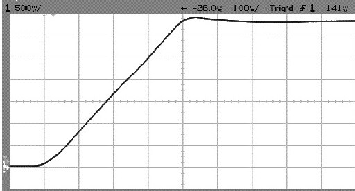
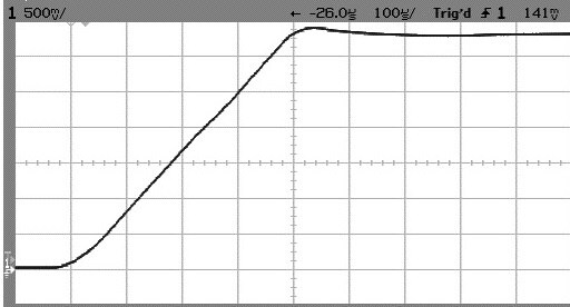
Here's the rise time photo:
Rise time is about 0.4 mS, and is very smooth (no sharp increase along the way.
Hi Robert,
Based on my experience, I don't see a problem with your supply rise time. However, I would say longer would be better if you can slow it down easily.
If you refer back to the pictures at the beginning of the thread, you can see the two slope voltage rise we have, and I suspect that has some effect on the oscillator start up issue.
Regards,
Gordon Cook
Hi Gordon, Thank you for your observation.
Bob
I am experiencing the same problem.
In our system the complete DSP supply is switched with a FET from the main 3v3 line for energy consumption optimization.
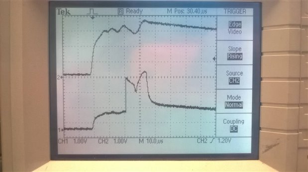
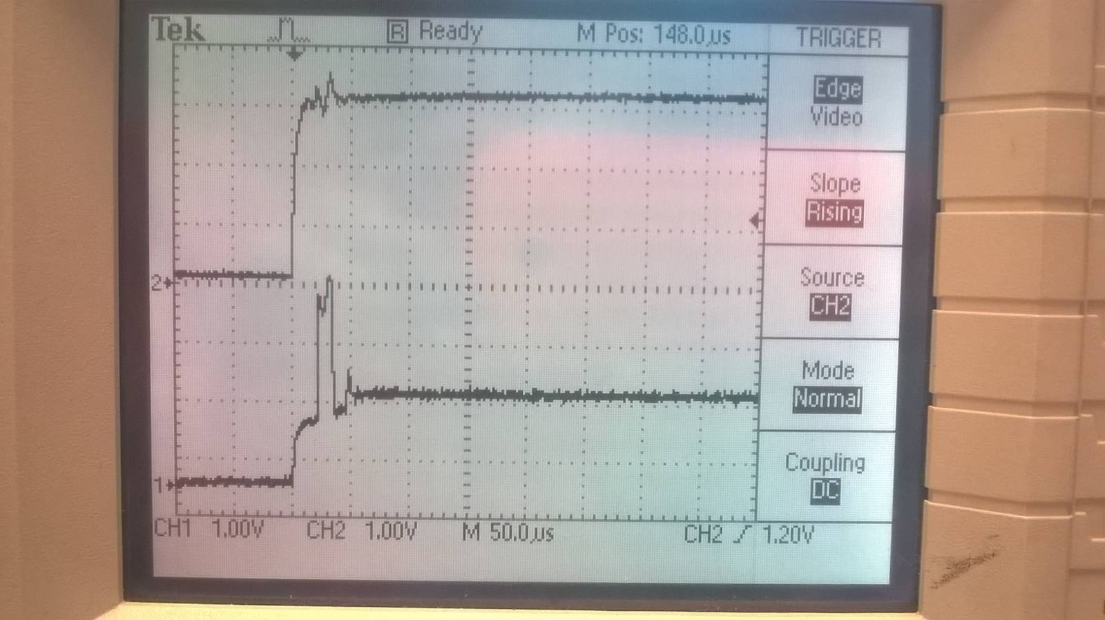
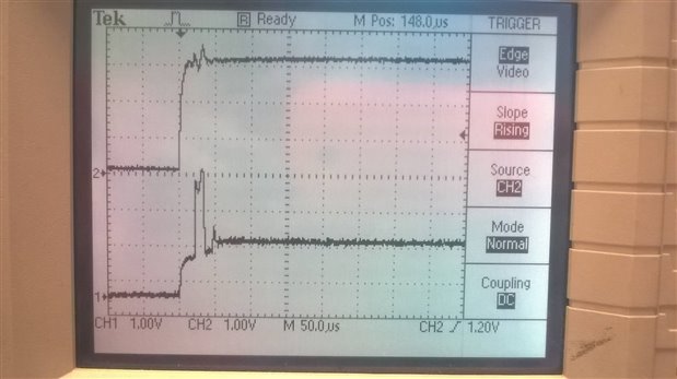
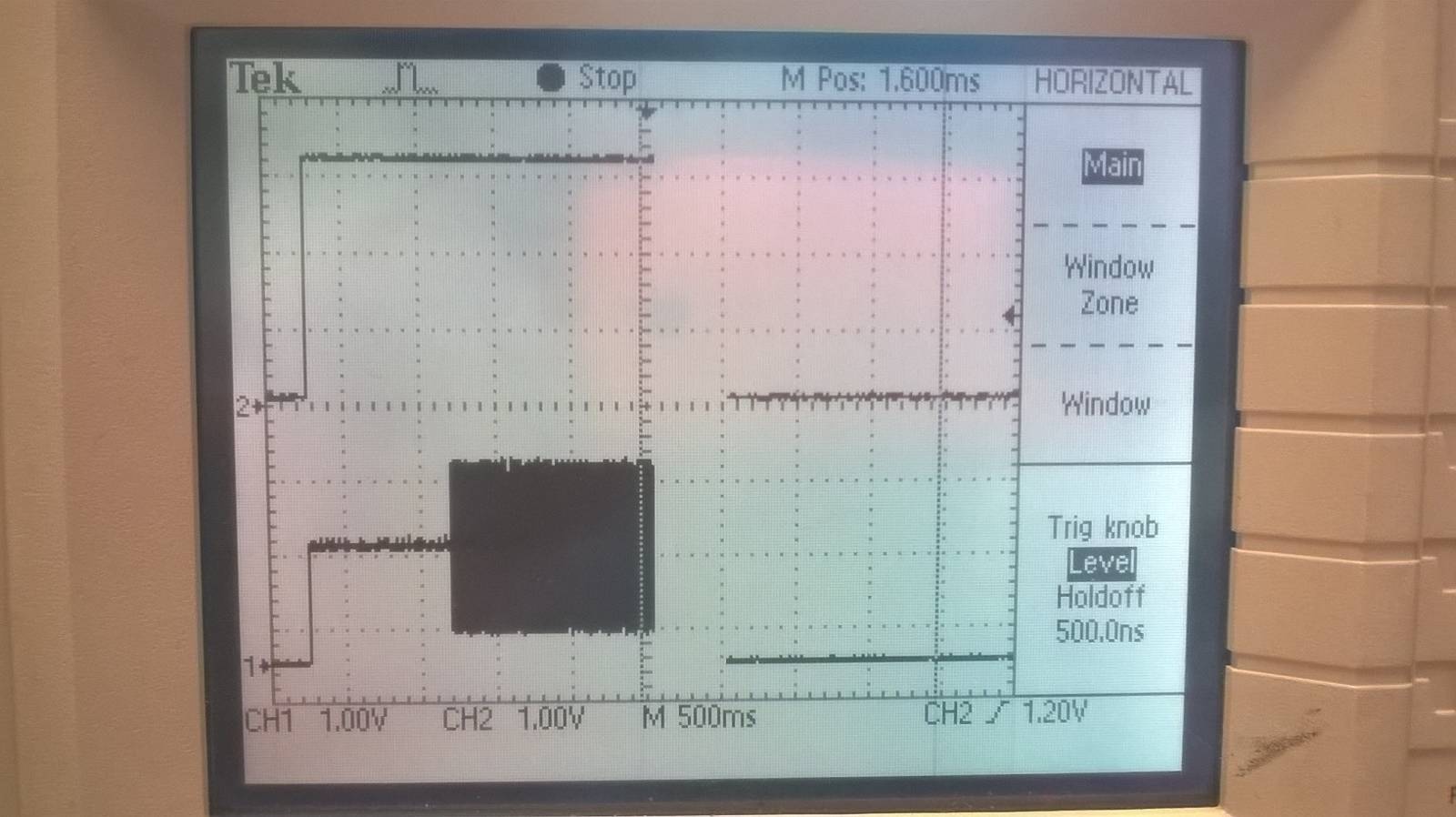
Rise times are short in our system, 10 - 40us. Oscillator does startup sometimes, but not always.
In the last picture you can see the oscillator starts after ~1sec. A bit long. Sometimes it will not start at all.
What is the recommended rise time for this part (ADAU1702)?

Hi,
I just saw your post.
From your screenshots, the oscillator is behaving similarly to what was observed with my circuit.
However the supply rise time is quite a bit faster in a few uSec instead of hundreds of uSec.
The oscillator appears to not have enough loop gain to start. In my case a physical shock or touching the oscillator connections was enough to start it.
We had another batch of DSPs that wouldn't start reliably. Again it was fixed by changing the rise time.
I suggest that if you can put a large enough cap on the supply to slow the rise time down significantly to more than 100 uSec you may see that they will start.
Please log in to reply.