ADAU1701 with 24.576MHz crystal?
Will the ADAU1701's oscillator work with a 24.576MHz crystal if the PLLMODE pins are both pulled high?
it looked like that should work, but upon re-reading it, I'm wondering if those settings are for an external buffered clock input only and that it requires a clock at 256*fs, and not 512*fs
Audio Signal Processors
SigmaDSP Audio Processors
adau1701
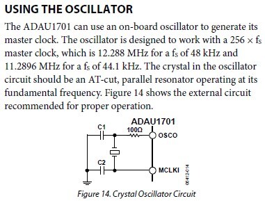
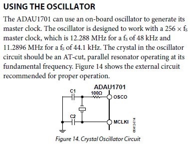
The crystal oscillator (driving a crystal) and the PLL are two separate entities. The PLL can accept a clock from an external source in the range of 3.072 MHz to 24.576 MHz, but that is coming from an external buffered clock. The crystal oscillator was only designed to work with a 12.288 MHz crystal.
For clarification, the datasheet plainly states that only a 12.288 MHz crystal will work:
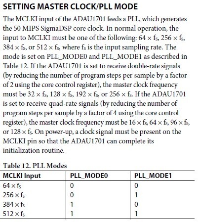
However, if you had an external buffered clock source, then you'd have a wider range of frequencies to choose from, by setting the PLL_MODEx pins accordingly:

Yeah, thanks. I came to that conclusion when things didn't work, but it's still not as clear as it could be. I misinterpreted it as an example, more than a specific requirement.
The Specification section should probably list any limitations on oscillator frequencies for the crystal.
Another slightly related note, is that specifiying the required 64,256,384,512 x fs numbers for normal operation, and giving different numbers for double and quad rate, but not having a "PLL Modes" table(12) for those other rates requires that the designer infer the mapping.
For example: If I was to do a double-rate setup my master clock frequency needs to be 32,128,192, or 256. I'll choose 256. Then if I look at the PLL Modes table, I see that for 256 I set the mode pins to 0,1. Nothing works, of course, because I need to know that I really want to set it to 512x fs.
There should be a more consistant way of naming things in the datasheet.
Probably the clearest and easiest would be to describe the PLL modes as 64,256,384,and 512 times the base sample rate, and omit the bits about 32x, 16x, etc. which are currently listed (without a clear mapping to the pll_modex pins)
This would also take care of the other point of confusion with the ADC resistors, which could be more clearly explained as needing to be scaled for changes in the base sample rate. Currently the bits about the Current based capacitive switching ADC make it look very clear that the resistors need to be scaled for double and quad rate, when that is not the case.
I agree with you 100%. That was definitely a stumbling point for some customers who did not want to use the plain old 12.288 MHz, 48 kHz setup. There are a few areas of the datasheet that need clarification, and I think you hit on them exactly.
That's why I wrote the ADAU1442/ADAU1445/ADAU1446 datasheet in a way that clearly states the difference between base sample rate, double sample rate, and quadruple sample rate, and describes the clocks as multiples of the base rate, rather than the "audio sample rate" which can be deceiving because it depends on register settings. This follows your suggestions. I'm planning on writing all future SigmaDSP datasheets in the same way, as well.
I wanted to go back and update the ADAU1701, ADAU1702, ADAU1401, and ADAU1401A datasheets, but at the moment it has been really difficult to fit that into my schedule!
Please log in to reply.