Interface READ and WRITE
Hello Brett,
I have an arrangement as shown in the attached file. I have implemented a simple stereo switch that toggles when a push-button connected to a GPIO is pressed. I have used an LED as a visual indication of the stereo channel that is selected. All works fine except that the last position of the stereo switch is not restored on power-up.
Kindly advise.
kksl
Hello Brett,
Any thoughts on what I could be doing wrong?
The last state is not retrieved on next power-up. I can post the project file if it helps.
Thanks in advance.
KKSL
Hi KKSL,
The code for generating the self-boot EEPROM image was re-written a few years ago due to some issues customers were reporting. It appears that this code update fixed some problems, but may have inadvertently broken the interface read-write functionality in the process.
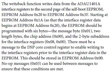
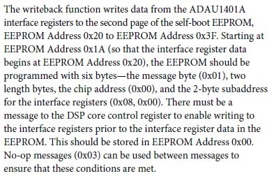
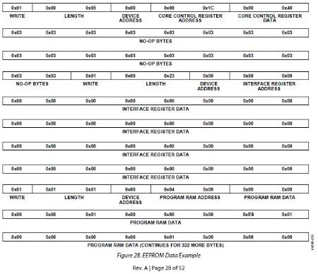
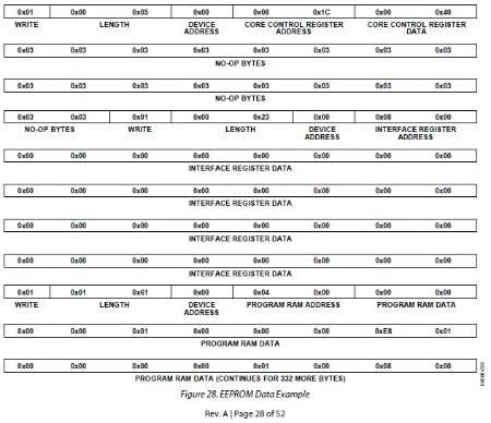
If you read the datasheet description of the interface registers and the EEPROM format, it says that the interface data must be stored in very specific locations in the EEPROM in order for the interface read/write functionality to work properly.
Here is the corresponding section of the datasheet:
And the corresponding figure:
Unfortunately, if you check the generated EEPROM file from any SigmaStudio 3.x build, it's clear that the data format does not quite meet these conditions. Here's an example that I compiled today:
0x01 , 0x00 , 0x05 , 0x00 , 0x08 , 0x1C , 0x00 , 0x58 ,
0x03 , 0x03 , 0x03 , 0x03 , 0x03 , 0x03 , 0x03 , 0x03 ,
0x03 , 0x03 , 0x03 , 0x03 , 0x03 , 0x03 , 0x03 , 0x03 ,
0x03 , 0x03 , 0x01 , 0x00 , 0x23 , 0x00 , 0x08 , 0x00 ,
0x00 , 0x00 , 0x00 , 0x00 , 0x00 , 0x00 , 0x00 , 0x00 ,
0x00 , 0x00 , 0x00 , 0x00 , 0x00 , 0x00 , 0x00 , 0x00 ,
0x00 , 0x00 , 0x00 , 0x00 , 0x00 , 0x00 , 0x00 , 0x00 ,
0x00 , 0x00 , 0x00 , 0x00 , 0x00 , 0x00 , 0x00 , 0x00 ,
0x01 , 0x00 , 0x13 , 0x00 , 0x00 , 0x00 , 0x00 , 0x00 ,
The bytes highlighted in bold, according to the datasheet, should be 0x00 0x40. However, you can see that they have been written as 0x00 0x58.
EDIT: This is not the issue. The same bit (IFCW) is enabled in both cases. It is no problem for the value to be 0x00 0x58.
The interface registers themselves (in italics), appear to be in the proper location.
Today, I will try to manually update the file to see if I can successfully use the interface read/write functionality.
Message was edited by: Brett Gildersleeve
KKSL,
I was able to get this working on my board. Unfortunately, it does require some manual manipulation of the EEPROM image file. It might take a while for me to explain. I'm thinking about doing a video to explain the step-by-step method because that would be easier than writing a very long post. I will let you know in a few days what I plan to do.
Best Regards,
Brett
Thank you so much Brett, I look forward to it!!
I am now one step away from implementing my entire project without a micro-controller.
Kindly take a look at my feature request, that I have made in my private message to you, and bless it.
Do let me know if you need more clarity on what I want.
Thanks in advance!!
Regards,
KKSL.
Hi KKSL,
The guide to using the interface registers and write-back functionality is here:
Please log in to reply.