Request Mod to use ADUSB1 with AD1701 eval board instead of USBi
Hello Brett,
I have ADUSB1. Since USBi is a little inconsistant a the moment, I was thinking of using the ADUSB1 with the AD1701 eval board.
Even if the mod to do so is an active ckt (around TC7WH241/ 74lvc5411D), I will power it up on a daughter board.
Attached is the ADUSB1 to SPI interface. I need ADUSB1 to I2C interface.
This way I can bring my earlier investment to life and also be able to continue some interesting work using the eval board till we find a solution for USBi.
Somehow, I don't seem to find the FTDI drivers for the ADUSB1. Kindly also provide me a link where I can download the same.
Thanks in advance for all your support.
Regards,
kksl
p.s. I found the ADUSB1 SPI/ I2C Interface. I will create a mod and post it for your approval. Still cannot fint the FTDI drivers though...so still need your help there.....
Hi KKSL,
The FTDI drivers should be located in the install directory for SigmaStudio. Please check my installation here:

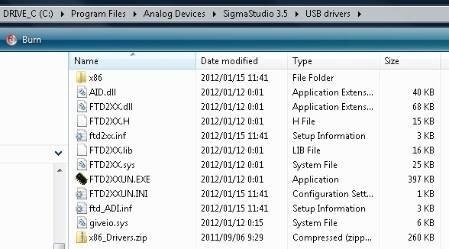
Thanks!! Good that the drivers are still part of the bundle.
It looks like the mod is pretty straightforward.
Pin-2 of ADUSB1 connects to Pin-1 of J1 on USBi. This is the SCL signal.
Pin-9 of ADUSB1 connects to Pin-3 of J1 on USBi. This is the SDA signal
Pin-11 of ADUSB1 connects to Pin-4 of J1 on USBi. This is the 5V supply that will power the eval board.
Pin-18 of ADUSB1 connects to Pin-10 of J1 on USBi. This is the ground reference.
However, I have a few observations:
1. The SCL and SDA lines are pulled up to 3.3V using 10K resistor on the eval board. Hence no additional pull-up is required on the I2C lines near the J1 connector. But these lines are driven by 5V on the ADUSB1. I feel that the 10Ks are high enough to not load the 5V supply.
2. What about nRESET? Will this be required? If yes, which DSUB25F pin will connect to pin-6 of J1 on USBi?
If this mod is ok, I will go ahead with this. Kindly comment.
KKSL, I think you'll need some kind of level shifter in order to get this to work. The pull-ups to 5 V on the ADUSB1 will cause overvoltage on the SDA/SCL lines that could damage the ADAU1701. Also, the ADUSB1 was designed in 2004, before the ADAU1701 was even released, so I am not sure if the firmware code in the PIC will be capable of communicating with the ADAU1701 in I2C mode. I'm pretty sure the ADUSB1 was hard-coded to interface with the AD1940 in SPI mode only, but I'm not certain, since that code was written before I became an employee here.
Why don't we avoid the headache and just arrange to replace your USBi with a new version with updated firmware? This new firmware seems to be much more stable than previous versions. If that really doesn't fix the problem, then I can arrange to replace your USBi with new version of the hardware when it is finished.
Please log in to reply.