Check µC values with USBi?
Hi,
our plan is to make an A-Sample PCB consisting of an ADAU1702 and a µC (STM32F100, Cortex ARM3).
The ARM should load the program and parameters into the 1702 and also change some parameters (filter coefficients) over an SPI connection.
I saw that with SigmaStudio I can read/write parameters from the 1702 specifying address and byte count (hardware tab).
The question is can I connect both the µC and the USBi to the 1702's SPI and check whether the µC has written the correct values?
Of course when reading with the USBi the µC must stop reading on the SPI.
Regards
Christian
Audio Signal Processors
adau1702
SigmaDSP Audio Processors
Hello,
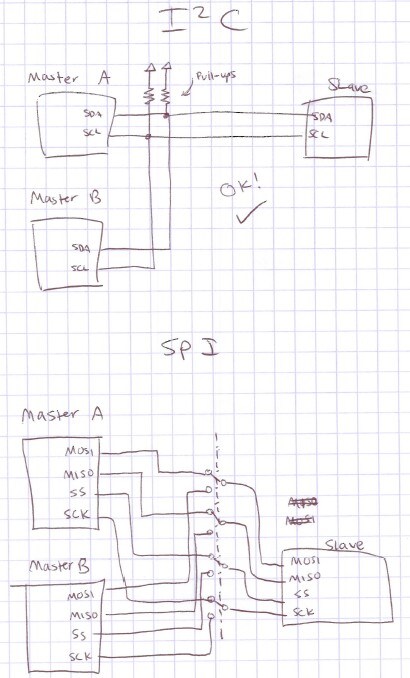
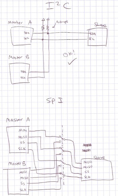
Using the I2C protocol, this is much simpler, because you can have several master devices on an I2C bus. When the master is inactive, it will simply "release" the bus by making its I2C lines high-impedance, which allows another master to take control.
If that is not an option, and you must use SPI, then the situation becomes a little more difficult. SPI masters will always actively drive the SPI lines. So, if you have two masters on the same bus, there will be bus contention, and communications will be impossible. You need to create a switch that will phyiscally disconnect each device from the bus, so that only one is active at a given time.
Ok, thanks!
Hi,
meanwhile I've managed to read values over SPI with the USBi.
The question for the ARM is now how long the CLATCH signal must be low and high (3 times) to enable successfully the SPI mode? I can't find any value in the technical data on this.
Regards
Christian
Christian, the datasheet should list a maximum clock frequency for the SPI port. Edges on the CLATCH signal will be detected as long as the frequency of the edges is at the maximum clock frequency or below. For the ADAU1702, this is listed as 6.25 MHz, or a period of 160 ns. So, you need at least 160 ns between the edges of the toggling CLATCH signal in order for it to be detected.
Please log in to reply.