Relationship of DC Input Entry cell and real-world DC Voltages
Could you please help me to understand more about the module of DC Input Entry? What’s the relationship between the value input and the DC voltage output? For example, if I want the SigmaDSP to output a 3.0V DC, what value should be set in the DC cell?
gpio
SigmaDSP
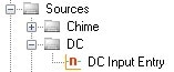
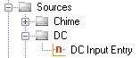
The DC Input Entry cell exists inside the SigmaStudio signal flow and represents a value stored in RAM. It does not represent a real-world DC voltage. It is typically used to create a constant number inside the DSP. That number can be used to control the logic cells inside SigmaStudio’s signal flow.
The number format of the cell can be modified so you can generate any value and store it in RAM. An explanation of number formats is here: https://ez.analog.com/message/13377#13377
The DC Input Cell can, of course, be routed to outputs in SigmaStudio like serial port outputs, DAC outputs, or GPIO outputs. This will allow you to interface it to the outside world.
The DACs on SigmaDSPs have an AC-coupling output, so you should not use them to generate a DC output signal.
(Note: The ADCs on SigmaDSPs are also AC-coupled, so they cannot accept DC inputs.)
Serial outputs (I2S outputs or TDM outputs) can be used to output a DC Input Cell value to the outside world. If you feed a DC Input Cell to a serial output, then that serial output will generate the 24-bit encoded version of that value and output it for every sample on the I2S output stream. Again, an explanation of number formats is here: https://ez.analog.com/message/13377#13377
GPIOs are digital, so they can only have two output voltages… GND and IOVDD. It is impossible to output any other voltage on a GPIO. If you feed a DC Input Entry cell to a GPIO output in SigmaStudio, there are two possible settings: zero, or NOT zero. If you set the DC cell to zero, then the GPIO will output GND. If you set the DC cell to any number other than zero, then the GPIO will output IOVDD. (polarity can be inverted on some SigmaDSPs using register settings)
The Auxiliary ADCs on SigmaDSPs are DC-coupled and are designed to input DC signals. You can put a DC signal on the aux ADC and it will show up in the DSP core. (Here is an explanation of how the auxiliary ADC data is formatted: https://ez.analog.com/message/29768#29768 )


This question has been assumed as answered either offline via email or with a multi-part answer. This question has now been closed out. If you have an inquiry related to this topic please post a new question in the applicable product forum.
Thank you,
EZ Admin
Please log in to reply.