uC programming a Sigma DSP
Hello
I'm work in a project that I need to create a code for a TEXAS DSP (TMS320F28335) that this code will make a sigma boot.
For start to do it the first thing that I did is read the pdf "SigmaStudio Basic uC Integration Tutorial.pdf"
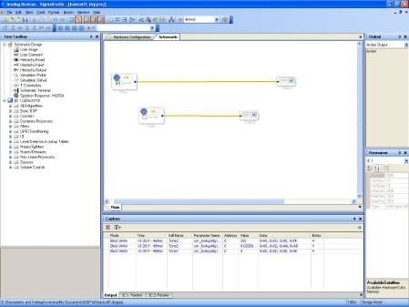
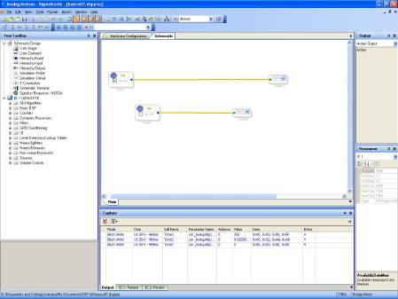
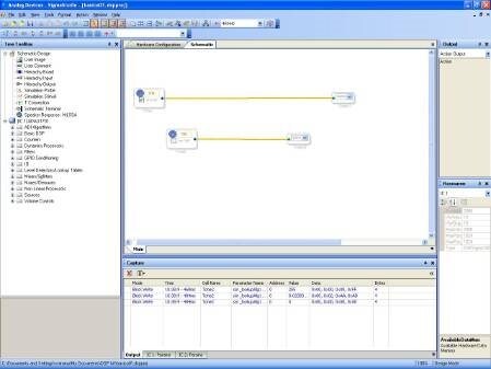
After read it I did the same program at Sigma Studio Like This.
This work fine....I can program My sigma and listen the beep!.
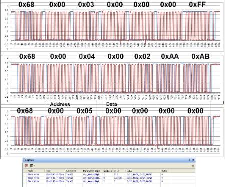
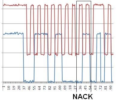
To understand the I2C communication I plugged My Oscilloscope at pin 1 SCL and pin 2 SDA and I click at box mute in Sigma Studio and I saw this!
I know that is so beautiful..
Now I saw what I need to do with My uC to make a mute in my sigma.
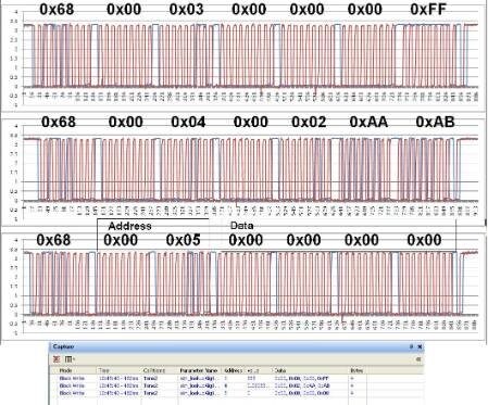
and I try to create the same waveform, and I did some thing similar!
My waveforme without plug at sigma!
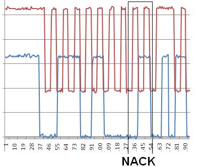
At this picture you can see that I dont have the ACK because I did plugged the SCl and the SCL!
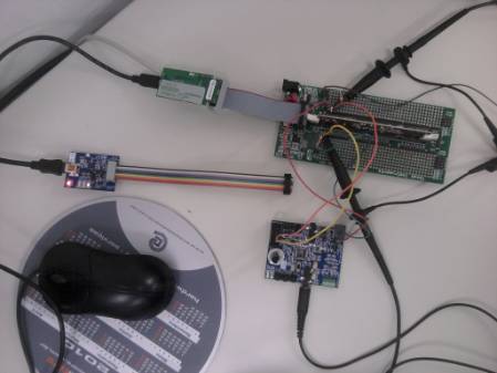
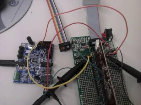
Now I thought the is the time to plug the uC at the sigma and I tried to did it!
At First point I write my program at EPROM and now I don't need the SigmaStudio to listen the beep, I just need to change the S5 to EPROM and turned on the Sigmakit (EVAL-ADAU1701MINIZ).
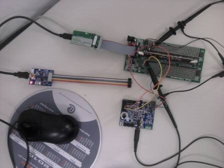
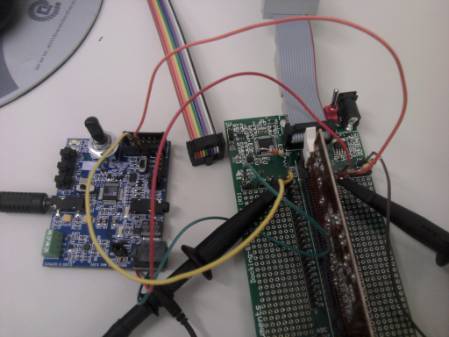
After I did it I plugged the SDA and the SCL at J8 connector at pin 1 and 3 and I did my uC write the 0x68 at sigma!
But I dont have the ack again!!!
My question is:
Is correct to plug my SDA and SCL at J8 and the switch S5 for the EPROM side?
Do you know If I need to plug another wire At the J8?
Is possible Do it, make the boot with the EPROM and after try to write a address by I2C to change some parameter?
Do you know if I was missing something?
Thanks For all
and sorry about my English!

I'm glad that example project worked well for you! It's good to hear that people are able to make use of it.
Everything looks set up correctly on your hardware. Your procedure sounds correct to me. I can clearly see the 0x68 and the NACK on the I2C line in your scope shots. That's very strange that you are getting a NACK. I have a few questions:
How long is the ADAU1701 powered on and running before you try to communicate with the TMS DSP? What I really want to know is: Has enough time passed for the EEPROM self-boot to complete?
Have you checked the I2C lines with your oscilloscope when you power on the ADAU1701 to make sure that the EEPROM self-boot occurs?
Is the TMS DSP hooked up to the ADAU1701 board during the self-boot? I am wondering if maybe the TMS DSP board is loading the lines somehow, which would possibly prevent the self-boot from proceeding successfully.
The wires are a little long. I wonder if noise might be an issue. Try, if possible, to use shorter wires. Also, make a local ground connection on the USBi header (pin 10) and run that over to the TMS DSP board. I'm just thinking of ideas to help reduce noise on I2C.
Hello Brettg
Thanks for reply!
How long is the ADAU1701 powered on and running before you try to communicate with the TMS DSP? What I really want to know is: Has enough time passed for the EEPROM self-boot to complete?
I know that I'm waiting the self boot because I can listen the beep!
Have you checked the I2C lines with your oscilloscope when you power on the ADAU1701 to make sure that the EEPROM self-boot occurs?
I know that It is working
Is the TMS DSP hooked up to the ADAU1701 board during the self-boot? I am wondering if maybe the TMS DSP board is loading the lines somehow, which would possibly prevent the self-boot from proceeding successfully.
Maybe this is the problem that I have.....know I dont know what I did....maybe I put my DSP TMS at debug if the correct pin voltage and after I power up the sigma.....but Know I have the ack!!!!
The wires are a little long. I wonder if noise might be an issue. Try, if possible, to use shorter wires. Also, make a local ground connection on the USBi header (pin 10) and run that over to the TMS DSP board. I'm just thinking of ideas to help reduce noise on I2C.
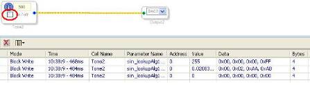
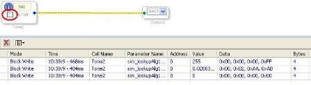
That Is not My problem! I did a program that make a beep on and after beep off....and now it is working!!! I did the self boot by EPROM and After I sent the parameter like the picture!
I will make the funcion correct! and After I will sent to here.....mabe this all work can help some on!
Brettg another question....If I will program the sigma by my DSP Do you know if have a time after to power the sigma to write the program?
example I put the sigma on....after 10 mim I decide to program by i2c......Can I do it? or I need Put the sigma on and write fast the program?
Thanks for all help.
Maybe this part of funicion will help other people to create the SIGMA_WRITE_REGISTER_BLOCK.
This Funcion work in a TMS320F28335 in a free data mode I2C.
Uint16 SIGMA_WRITE_REGISTER_BLOCK(int devAddress, int address, int data_Length, const void* dados)
{
ADI_REG_TYPE *pointer = (ADI_REG_TYPE *)dados;
ADI_REG_TYPE address_MSB = 0x00;
ADI_REG_TYPE address_LSB = 0x00;
ADI_REG_TYPE j = 0x00;
// Wait until the STP bit is cleared from any previous master communication.
// Clearing of this bit by the module is delayed until after the SCD bit is
// set. If this bit is not checked prior to initiating a new message, the
// I2C could get confused.
if (I2caRegs.I2CMDR.bit.STP == 1)
{
return I2C_STP_NOT_READY_ERROR;
}
// Check if bus busy
if (I2caRegs.I2CSTR.bit.BB == 1)
{
return I2C_BUS_BUSY_ERROR;
}
I2caRegs.I2CMDR.all = 0x4628;
address_LSB = ((ADI_REG_TYPE) (address & 0xFF));
address = (address>>8);
address_MSB = ((ADI_REG_TYPE) (address & 0xFF));
// Setup number of bytes to send
// MsgBuffer + Address
I2caRegs.I2CCNT = data_Length+3;
I2caRegs.I2CMDR.all = 0x6628 ;
while(I2caRegs.I2CSTR.bit.XRDY != 1);
{
I2caRegs.I2CDXR = devAddress;
}
I2caRegs.I2CMDR.bit.STP = 1; //Ja pode setar o stop bit, ele so é gerado quando o contador acabar...
while(I2caRegs.I2CSTR.bit.XRDY != 1);
{
I2caRegs.I2CDXR = address_MSB;
}
while(I2caRegs.I2CSTR.bit.XRDY != 1);
{
I2caRegs.I2CDXR = address_LSB;
}
// I2caRegs.I2CMDR.all = 0x6628;
for (i=0; i<data_Length; i++)
{
while(I2caRegs.I2CSTR.bit.XRDY != 1);
{
I2caRegs.I2CDXR = *pointer++;
}
}
for (j = 0 ; j < 3000; j++);
return I2C_SUCCESS;
}
1 More problem.
Now I can make the sigma boot and I can change block parameter by I2C.
Now I make by my DSP(TMS320) the Sigma BOOT and in this BOOT contain the sigma program like the SIGMA STUDIO image.
I did it with this part of code.
// PROGRAM SIGMA BOOT
default_download() ;
// Application loop
for(;;)
{
//MUTE THE BEEP
SIGMA_WRITE_REGISTER_BLOCK( DEVICE_ADDR_IC_1, MOD_TONE2_ALG0_ON_ADDR, MOD_TONE2_ALG0_ON_SIZE, &TABLE_MOD_TONE2_ALG0_OFF_FIXPT[0] );
//UN-MUTE THE BEEP
SIGMA_WRITE_REGISTER_BLOCK( DEVICE_ADDR_IC_1, MOD_TONE2_ALG0_ON_ADDR, MOD_TONE2_ALG0_ON_SIZE, &TABLE_MOD_TONE2_ALG0_ON_FIXPT[0] );
} // end of for(;;)
}
Ok, the problem that I have is when I make the BOOT.
// PROGRAM SIGMA BOOT
default_download() ;
It work like the SIGMA STUDIO program, and I can Listen the BEEP very well.
but when I try to mute and um mute by my code (My DSP) it don't work like the sigma studio.
when I make the mute by the code.
//MUTE THE BEEP
SIGMA_WRITE_REGISTER_BLOCK( DEVICE_ADDR_IC_1, MOD_TONE2_ALG0_ON_ADDR, MOD_TONE2_ALG0_ON_SIZE, &TABLE_MOD_TONE2_ALG0_OFF_FIXPT[0] );
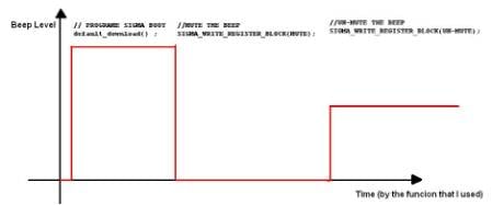
its work like the sigma, but when I UN-MUTE the sound back but
lower
//UN-MUTE THE BEEP
SIGMA_WRITE_REGISTER_BLOCK( DEVICE_ADDR_IC_1, MOD_TONE2_ALG0_ON_ADDR, MOD_TONE2_ALG0_ON_SIZE, &TABLE_MOD_TONE2_ALG0_ON_FIXPT[0] );
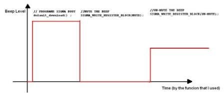
The graphic below show the Beep Level after execute the function.
This is a video that you can listen the different beep level. after UN-MUTE this beep if very LOWER maybe you will need put the PC Volume high.
Thanks For All Help.
Can you please share the exact register writes for BEEP ON and BEEP OFF?
For example, the sequence file or at least a description of the register writes?
This question has been assumed as answered either offline via email or with a multi-part answer. This question has now been closed out. If you have an inquiry related to this topic please post a new question in the applicable product forum.
Thank you,
EZ Admin
Please log in to reply.