1442 Signal I/O Volume
Hey guys, I have been messing with the analog IO on the 1442 EVAL board and I am confused about the IO signal levels.
I input a 1k sine wave at 1v p-p and rout it back out to an output and measure it, the signal is almost half as powerful. ie dropped to 0.5v p-p.
Can anyone explain why it is cut in half? And solutions to overcome this? Linear Gain factor of 2 inline?
Thanks,
Jason
The AD1938 is used for A/D and D/A conversion on the evaluation board. You can see from the AD1938 datasheet that the full-scale input and output levels are not equal:
Adding 6 dB gain in the DSP would simply clip the outputs, causing massive distortion.
Scaling the signal down by 6 dB prior to the ADC and scaling it up by 6 dB in the DSP will increase your noise floor by 6 dB.
In other words, scaling the signal in any way will compromise audio performance.
In a real system, you could design active output filters so they have a linear gain that brings the signal back up to the level you require.
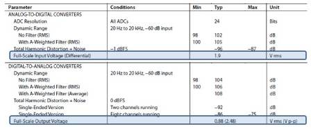
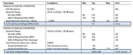
Hmmm. So ther is now way to balance them out? Not even close? That doesn't seem very practical. Maybe its just me.
Jason
I am planning to run the output of one eval board into the input of another and then out again. could I add 3dB on the output of one and 3dB on the input of another to help balance it out?
Jason
The discrepancy in level is due to the fact that the inputs to the AD1938 are differential and the outputs are single-ended. In order to maximize the signal-to-noise ratio of the product, different levels are required to maximize voltage swing within the allowable supply range.
Typically the codecs are only used when you're connecting to the outside world. Conversion from one domain to the other always generates noise, so doing ADC - DSP - DAC - ADC - DSP - DAC leaves a lot of places for the noise of the system to increase.
I would suggest instead doing what you would do in a real system with multiple DSPs in series: connect the DSPs with a digital interface.
You have two options on the ADAU1442: I2S or S/PDIF. For I2S you basically need to connect the LRCLK, BCLK, and SDATA_OUT of your first DSP to the LRCLK, BCLK, and SDATA_IN of your second board. One DSP needs to be master and the other needs to be slave. For S/PDIF you can take the S/PDIF transmitter of one board and connect it to the S/PDIF receiver of the second board. In both cases, you're probably not running the two boards in sync with the same master clock, so you will have to use the ASRCs in order to avoid synchronization errors.
Interesting idea. Your right, I am not running the boards in sync. Infact they will be in two different physical locations. The data signals will be transmitted via fiber optic lines.
Can you explain ASRC's? Forgive my ignorance. Also does the 1442 have both a S/PDIF transmitt and receive?
Thanks,
Jason
ASRCs are used to convert between different sample rates or to safely pass data between two ICs that are not in sync. There is a lot of detail about them available in the datasheet: https://www.analog.com/static/imported-files/data_sheets/ADAU1442_1445_1446.pdf
Info on S/PDIF Tx/Rx setup can be found here: https://ez.analog.com/message/13376#13376
mtbrider405 wrote:
Ok, thanks for the info Brett.
I was looking at the voltages specs from the data sheet, and as long as my input voltage is not higher than the DAC output capabilities, I should hot see a loss correct?
The DAC can output 0.88 Vrms so as long as my input doesn't exceed that, I can reproduce any signal I put in at the output correct?
Thanks,
Jason
We're doing two domain conversions. We convert once in the ADCs from the analog to the digital domain, then we convert again in the DACs from the digital domain to the analog domain. Every time you do a domain conversion, there is the concept of a full-scale reference. Full-scale means that "a signal at this voltage corresponds to 0 dB in the digital domain, which is the largest signal that can be represented". Any signal above this level in the analog domain corresponds to a clipped signal in the digital domain. In the AD1938, the two domain references are different. The ADCs are referenced to one level, and the DACs are referenced to another. This means that you will always see scaling on the signal if you pass it directly through. The signal scaling in the system equals (DAC full-scale reference / ADC full-scale reference).
The only way to avoid signal scaling is to choose an ADC and a DAC that have exactly the same reference level.
So, to answer your question, the DAC has no knowledge of the ADC's input reference level, so the signal reproduced on its output will be at a different level than the one on the ADC input.
In a real system, if you require the same level on the analog output as you do on the analog input, the best way to handle that is to use a low-noise amplifier on the DAC outputs to scale the signal accordingly.
This question has been assumed as answered either offline via email or with a multi-part answer. This question has now been closed out. If you have an inquiry related to this topic please post a new question in the applicable product forum.
Thank you,
EZ Admin
Please log in to reply.