Need help building Intelligent Signal Router
Ok guys I am new around here. I searched for a similar situation and could not find one so I'm asking for help.
I am new to SigmaStudio and to Sigma DSP's. I bought the 1442 EVAL board. My goal is to use the board to prototype my system design then design my own board using the same components.
First I will do my best to describe the system as a whole. I am working with a team of 4 people to design a redundant communication system. At one end and FSK modem will output a signal (alternating frequency sine wave) to card 1. Card 1 will mix an out of band tone with the incoming signal and output the new mixed signal on two outputs. These two outputs are sent to two independent fiber optic lines and transmitted to the remote end.
At the remote end, the two analog signals are sent into card 2. Card 2 will separate (using filters) the FSK signal and the out of band signal. The RMS of the out of band signal will be checked against a threshold value to determine if the line is healthy and if one of the out of band signal's RMS falls below the threshold the other FSK signal will be sent to the output of card 2.
This is were I am having the problem. The mixing of the FSK signal and the out of band tone in card 1 seems like it should be a no brainer and the filtering of the two signals in card 2 is easy as well.
I cannot figure out how to build this intelligent signal switcher in card 2. The key is, if the system switches the output from say channel A to channel B, it must stay on channel B until channel B goes down even if channel A comes back up in the mean time. Then it would switch back to channel A if B were to go down and stay on channel A even if B were to come back up. An so on.
I can't get myself to believe I can't do it in SigmaStudio, but I can't figure out even how to start going about this. I have tried using a multiplexor to control switching between the two incoming channels and I still feel like that's the way to go, but I cannot figure out how to drive the multiplexor based on the switching characteristics described above.
Any help would be much appreciated! I have attached the SigmaStudio file I have been working on for Card 2 but it has no switching logic included.
If any of this is unclear please let me know and I will do my best to help you understand it.
Thank you very much,
Jason
Ok I have been think about it and a NAND Latch sound more and more like a good idea to control the index controlled multiplexor.
Has anyone come up with anyting else?
Thanks again for any help at all.
Just to be clear, could you describe in more detail the exact conditions you need for selecting either channel A or B? Once I understand that, I can help you select the right cells in SigmaStudio's library.
Hey Brett. Thanks for the reply. I would love to have your help!
Ok so again, a quick overview. The card will read in two identical signals. They are composed of an FSK signal and an out of band tone that has been mixed with the FSK signal at another location.
This card will filter the FSK signal and the out of band tone into two separate signals. The FSK signals are not transmitted constantly so the out of band tone is transmitted at all times in order to monitor the heath of the channel. Based on the RMS or health of the out of band tone, the card will decide which channel to pass to the output, A of B.
As far as switching goes, I don't care what which channel is in use as long as it is healthy. My main concern is that it must remain on whichever channel it is on until the that channel fails the heath check.
So for example. Lets say the system initializes to channel A and both lines are healthy. In other words the card is outputting the signal from channel A. (It could potentially run like this for weeks) Now lets say a backhoe digs up the fiber for channel A. I want the card to switch its output to signal from channel B. Pretty basic right? Now we are running on channel B for a while as we are fixing the fiber for channel A.
Now all of the sudden, channel A comes back up and the card sees channel A as healthy again. Even though channel A is back up, I want the card to not switch to channel A until channel B fails. Then it would remain on channel A until A fails again at some point and so on.
I hope this clears it up a bit. Like I said I have been looking into NAND latches and it appears they will handle the logic I need.
What do you think?
Thanks in advance for your help.
Jason
What you want is a state machine. Check SigmaStudio modules under Muxes/Demuxes->State Machine. I think there is an example of it in the help files too.
Thanks for the reply magicrub. I looked into the state machine's operation and it made sense, but I couldn't see how it would fit into the control logic for the mux. Could you provide a little more insight as to how to implement this block into my logic.
Thanks,
Jason
Hey Brett, did my extra description clear things up for you at all?
Jason
Due to some other priorities I wasn't able to examine this issue any further this week. I will do my best to devote some time to it next week. Have a nice weekend!
Ok thanks a lot Brett for even being willing to help. We should have our eval board in this week and I will try to get an updated version of my code up for you to look at this coming week. Everything has been closed down in OKC due to snow, so I haven't been able to work much either. Just downloaded SigmaStudio onto my laptop so I will have something up soon.
Thanks again,
Jason
Jason, I finally got some time to ponder this question a bit. I have a few basic questions that I need to understand before I can move forward:
How many total channels are there? In your example above, there are two channels, A and B. Will there potentially be any more channels than that? C? D?
How would you quantitatively define a "healthy" signal? The SigmaDSP doesn't have the intelligence to know when it's getting a good signal input or a bad signal input, but you could help guide its judgement by making clearly defined quantitative conditions that define "health." For example, if I had some radio station and I wanted to define the health of the signal I would say that the RMS level of the signal must be above -60 dBFS for at least 3 seconds to be healthy, and has to dip below -60 dBFS for more than 5 seconds to be considered unhealthy. The logic behind that is that you're not going to want the radio station to go silent for more than 5 seconds, and since most programming is horribly compressed, any real program material will never go below -50 dBFS, I guess. So, that's just an example, but what are your conditions?
I think we can implement this pretty easily using basic logic and index multiplexers, depending on your answers to the questions above.
Hey Brett,
Sorry I was out of town since last friday. I can defiantly answer your questions so here goes.
1. There will only be 2 channels, A and B to choose from.
2. The way will tell if the signal is "healthy" or not is by measuring its RMS and comparing it to a user defined threshold. This system will potentially be implemented in large airports across the US. All that to say the lines used for transmitting are very stable and therefore I don't think we need to worry about the signal "disappearing" for a certain amount of time and then coming back. If the signal drops below the "threshold" we don't even want to attempt using that channel until it can be checked. It would just switch to the other "healthy" channel.
I hope that makes more sense. Let me know if you have more questions. I am back home now and will be able to give quick responses to questions.
One quick question off topic. How would I convert from one number format to another within the program? Like how would I drive an LED and the control input to a mux using the same logic? The logic blocks only seem to work in 5.23 format but the mux needs 28.0.
Thanks man. You a very big help to us.
Jason
I finally got a chance to work on this a bit.
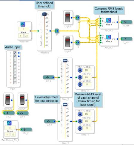
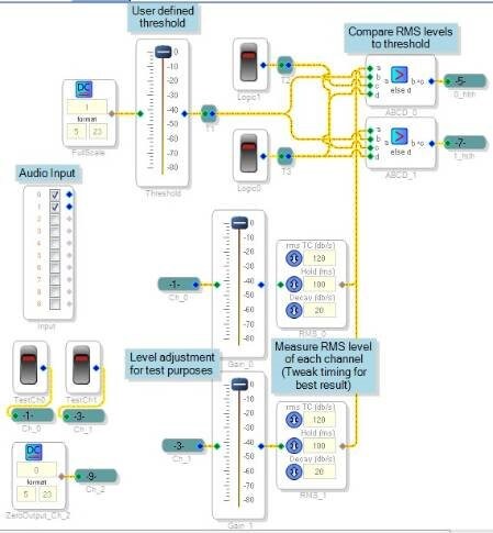
So far I've gotten the RMS detection scheme figured out, and I created a logic table for the output.
The detection scheme is simple. It produces two outputs, 0_hlth (boolean health of ch 0) and 1_hlth (boolean health of ch 1). I created ch 2, which is a zero output, or mute.
The logic truth table looks like this, where "Last Out" means the last valid signal that was output:
State
0
1
2
3
4
5
6
7
Last Out
0
0
0
0
1
1
1
1
0_htlh
0
0
1
1
0
0
1
1
1_hlth
0
1
0
1
0
1
0
1
Output
2
1
0
0
2
1
0
1
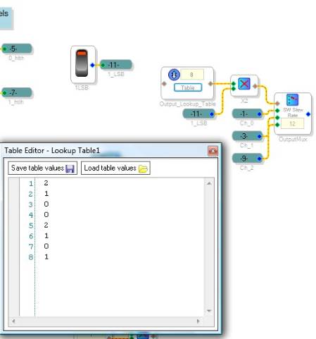
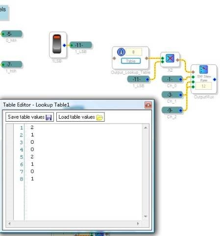
The output mux + index table looks like this:
Now I just have to figure out how to make those logic signals combine to create the "State" signal, which also involves the tricky feedback path for LastOut. Will work on it more when I have time. The project is attached in case you want to play with it.
Wow Brett, that looks great. The detection scheme is very similar to what I have come up with. Each channel produces a 1 or 0 depending on it being "healthy" or not. To take care of the "Last Out" problem I used the logic blocks and built an RS NAND latch with a few extra OR and NOR gates to prevent a double zero input to the latch since NAND latches don't like that. I am having a few problems with my design though. It is concerning number formatting. The logic blocks seem to need one numeric format, the mux control input needs another numeric format, and the GPIO outs to drive LED's use a different one than the mux. This leads me to these two main questions.
1. Is there a way to easily tell what numeric formats each block requires?
2. How can I drive two different block that require two different number formats with the output of one logic gate? Say, a mux and a LED (GPIO output).
I am not completely sure about the operation of the NAND latch. Mainly initialization. I think the channels will have to come "on line" in the same order every time for it to work right. I still need to test it. All that to say, would you mind continuing to work on your version of the switcher with the truth table you came up with? This way I can see another option and learn from it?
I really appreciate your work on this project. I am learning a lot!
I will post a copy of my program asap.
Thanks a ton!
Jason
You can see more about the number formats here: https://ez.analog.com/message/13377#13377
As a general rule, all audio in/outs use 5.23 format, and all control in/outs use 28.0 format. Some cells, like GPIO, work on a "zero or non-zero?" boolean logic, where an input of 0 is read as a false, whereas an input of anything but zero will be read as a true. A false is stored as 0 and a true is stored as 1 (in 5.23 format).
You can see some examples of converting between number formats here: https://www.analog.com/static/imported-files/application_notes/AN-951.pdf
Cool. Thanks Brett. Any more luck on the switching logic?
Thanks,
Jason
Ok Brett, check this out.
I have finished the initial program that will run on each card at each end of the communication system. Fiber optic lines will make the connections in between.
Other than the difference in full-scale operating range of the ADC and DAC, I think this should work. From what you have said I have gathered I will just have a weaker output signal than the one I start with unless I implement a low noise op amp at the outputs. I have been looking into the AD797 for that.
Here is the project file. If anything is unclear please just ask.
Thanks,
Jason
This question has been assumed as answered either offline via email or with a multi-part answer. This question has now been closed out. If you have an inquiry related to this topic please post a new question in the applicable product forum.
Thank you,
EZ Admin
Please log in to reply.