Index selectable filtering
Hi,
I've been trying to create a layout with an index selectable filter in, and have been trying to use a DC block to test the filter curve selection.
As far as I understand it, the 'General 2nd Order Index Selectable' block needs a 28.0 integer format index, so therefore needs a value of 0-10 (if 10 curves existed) in 28.0 integer format. This requires the DC block to output values of 0 for curve 0, 1 for 1, 10 for 2, 11 for 3 etc?
I have tried this a few different ways to no avail, and it's probably something obvious but still, can anyone help?
Nick
The values that you should enter in the dc block should be integers, not binary number. So, you should enter 0 for curve 0, 1 for 1, 2 for 2, 3 for 3 etc.
Hmm, ok thanks.
I have tried that approach, but I couldn't make the filter change and if I go past 4 then the output stops and the 7 band EQ shows that the <100 hz band is maxed out...
Could you post the project file you're using? If you have IP you don't want to expose, you could just cut out the relevant part of the design so that we can debug that.
I think I've figured out the problem. I'm trying to use an RMS table to output a value which I'm then using as the control input in the filter. What numeric format does the RMS table output in? I've told it to output 1-6 depending on the input signal level... should it be outputting integers or 5.23 etc?
The values in the rms table are in 5.23 format. If you want to use these values to select the indexes of your filter block, you should multiply your table values (0, 1, 2, 3, etc) by 2^-23 so that they're outputting the correct index values for the filter control.
ahh that's great. thanks!
Hi Jerad,
I'm back with another issue on this.
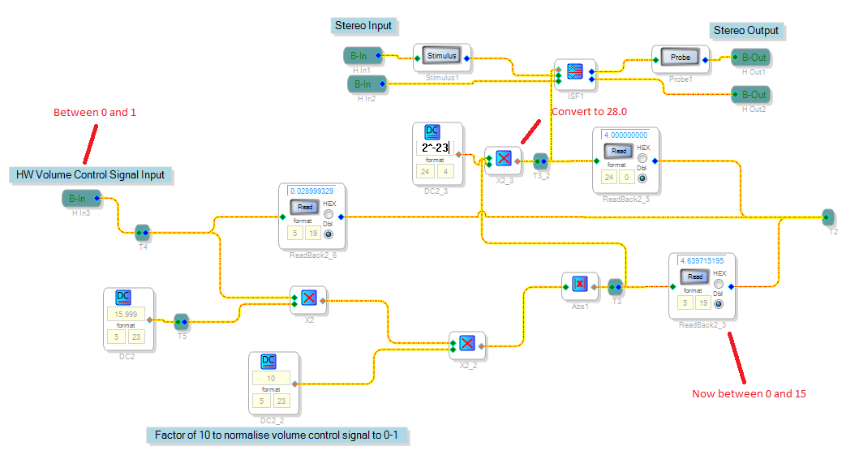
My sub layout is shown below. Im trying to convert values from 0-1 to between 0-15, then use this value to control an ISF block. I'm at a bit of a loss as to whats wrong here, can you help? As far as I know, I'm controlling the ISF block with a 28.0 signal between 0 and 15, yet it doesnt seem to change and doesn't show up on the probe as changing.
Thanks,
Nick
Please log in to reply.