How to get an high frequency triangle output?
Hello,
About the triangle wave generator of SigmaStudio, i have tested this at low frequencies using DAC output, the results are okay.
Have any problem if I define the frequency of triagular wave more than 20KHz (consider Fs = 96 or 192KHz)? Because I need in an app two triangle waveforms, but the frequency is about 48KHz.
The chip is ADAU1701.
Thanks,
Paulo
Audio Signal Processors
SigmaDSP Audio Processors
adau1701
Hi Paulo,
By setting the system sample rate, you will be able to create triangle waves at frequencies higher than 20 kHz. Here's an explanation of how to set the system sample rate:
How do I change the sample rate of my SigmaStudio system?
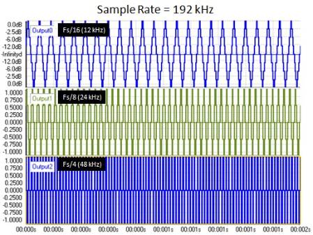
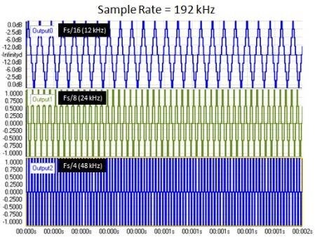
Here's an example of triangle waves at 1/16th, 1/8th, and 1/4th of the sample rate. Note that at 1/4th of the sample rate or above, there is no difference between a triangle wave and a sine wave because the harmonics are no longer included in the signal.
Thank you BrettG!
Your information is very helpful.
I think to use this triangle wave to generate an external PWM, comparing the audio with triangle wave I get an PWM on a external comparator output.
On this forum i see a discussion about the PWM generation for leds on GPIO - Can I generate the PWM with GPIO to use with audio (internally comparing the audio level with a triangle wave)?
The PWM carrier must have about 48KHz... It´s possible?
Thanks in advance.
Paulo
More information about the PWM implementation is here. It's definitely possible to jump the carrier up to 48 kHz, as long as your sample rate is 192 kHz.
https://ez.analog.com/message/12246#12246
I'm very sorry, but I missed a key part of your original post. If you're using the ADAU1701, you need to know that the ADCs and DACs will only work at 48 kHz sampling rate. If you increase the core rate to 96 kHz or 192 kHz, the converters will still be running at 48 kHz. In order to get an analog output signal at higher than 24 kHz, you'll need to use an external DAC that can run at 96 kHz or 192 kHz.
Thanks BrettG for your fast reply.
Yes, but I was thinking this PWM out in GPIO (without use the 1401´s DAC) it´s don´t possible?
I am a novice in DSP, sorry for some questions
Thanks in advance.
The GPIOs are updated at the sampling rate, so the fastest square wave you could output from these pins is 24 kHz (one cycle high, one cycle low). This is probably too slow to be used as a PWM output for audio. These GPIOs are intended for use as control interfaces such as lighting an LED or connecting external buttons. You can expand the number of channels on the ADAU1701 by using the serial data I/O ports to connect to other codecs or digital-input amplifiers.
Note: If you set the sample rate of the core to 192 kHz, you can get the GPIOs to output a maximum of 96 kHz. Still, as Jerad said, this is probably too slow to be used as a PWM output for audio.
Hello BrettG and Jerald,
The idea of use of triangle wave was to I compare (by external comparator) the audio with a ADAU1401 48KHz supplied triangle wave, then I output in external comparator the PWM carrier. But as you said, the DAC`s don´t work with this frequency of triangle wave ( I have tested this on eval board, in this case the triangle wave appears as a sinusoidal wave).
You said: "Still, as Jerad said, this is probably too slow to be used as a PWM output for audio"
The PWM carrier operating at 48KHz true is too slow to full-range audio (20Hz - 20KHz), but my circuit need only 20Hz ~ 5KHz range. It´s a class-D amplifier with PWM input, designed only for low frequencies.
I need use the ADAU´s processing, such as filters and volume controller. It´s already tested, okay. But I think to use ADAU to supply the PWM signal to source to power output stage of my project.
You Said: Note: If you set the sample rate of the core to 192 kHz, you can get the GPIOs to output a maximum of 96 kHz.
Then, I think based in this afirmation, is possible I get an 48KHz PWM output on GPIO on this chip (ADAU1401). Ok?
Because Jerald said: "The GPIOs are updated at the sampling rate, so the fastest square wave you could output from these pins is 24 kHz (one cycle high, one cycle low)..."
Thanks in advance.
Paulo
Jerad was referring to the 48 kHz case, where the maximum frequency you can generate in the core and on the GPIOs is 24 kHz.
If you set the core at 192 kHz, then the maximum frequency you can generate in the core and on the GPIOs 96 kHz.
The problem is that the carrier signal stops resembling a triangle wave at about fs/4.
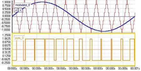
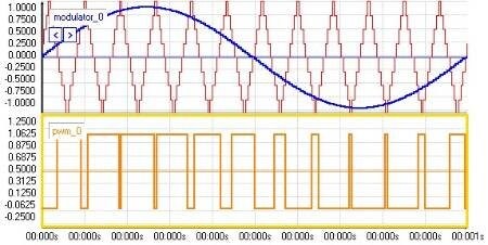
Anyways, I attached some examples of PWM so you can see the results. In all of these examples, the sample rate was 192 kHz.
Carrier = 12 kHz, Modulation = 1 kHz
Carrier = 24 kHz, Modulation = 1 kHz
Carrier = 48 kHz, Modulation = 1 kHz
Carrier = 48 kHz, Modulation = 5 kHz
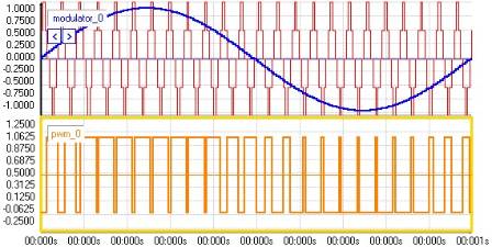
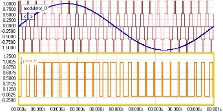
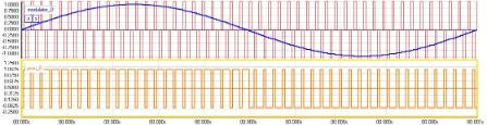
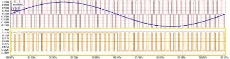
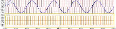
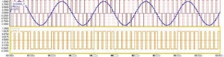
Also, be aware that the drive strength on the GPIO pins is only rated at 2 mA.
Hello Paulo,
I'm just curious if you managed it to drive a class D amp with this approach.
BrettG,
If I have the triangle on the GPIO pins and an audio signal on the DAC output, would both signal be synchron in relation to each other because of the sample rate ? What would be the delay between the signals ?
There will be a delay in the DAC due to the interpolation filters, but I'm not sure exactly how many samples. You can insert a delay in the project's GPIO path to compensate for this.
iPodから送信
Please log in to reply.