Converting values on ADC input port with lookup table?
I am currently using the signal on one ADC input port to control an index selectable multiband filter with 16 rows (see enclosed jpeg-file).
The signal on the ADC input port is generated by a 4-bit R2R-network. Obviously the R2R-network doesn't deliver the right values that are expected by the filter cell (e.g. it delivers a maximum voltage of 2.6 volts instead of 3 volts for full-scale of the ADC).
Is there any chance to convert the 16 values coming from the R2R-network with a lookup table? I have already tried several things, but nothing's seem to work.
Another application for such a conversion would be to convert the signal from a linear potentiometer into a logarithmic signal to control a SW volume cell.
I have already read the AN-951, where something similar is mentioned, but I have no clue to make it functionable for my project.
Any help is highly appreciated. Thanks in advance
Robin
P.S.: I use the ADAU1701
Audio Signal Processors
SigmaDSP Audio Processors
adau1701
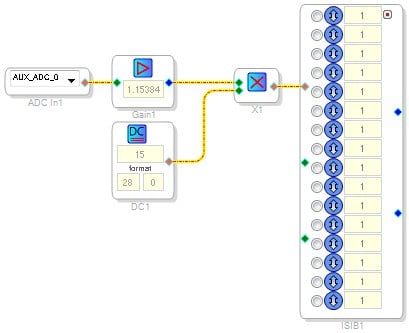
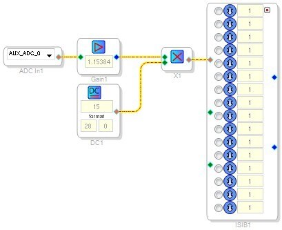
Is your potentiometer linear or logarithmic? If it is linear, then this shouldn't be too difficult. Your problem is basically that the full scale level of your signal is smaller than the expected level on the Aux ADC. So, all you'll need is a linear multiplication.
3.0 / 2.6 = 1.15384, so the signal flow essentially needs to look like this:
This example project from the AN-951 app note shows a project that works well on the EVAL-ADAU1701MINIBZ evaluation board and illustrates the operation of Aux ADC-driven indexing.
Thanks a lot for the info. I tested it last week and the multiplication works fine, but now the next problem occured.
My simple 4bit R-2R network is everything else but precise, means that the relation between each of the bits is not correct. (LSB delivers 0.227 volts, 2nd bit delivers 0.411 volts, 3rd bit delivers 0.76 volts and MSB delivers 1.41 volts).
The R-2R network drives an multiplexer, which gets "confused" by the unprecise values. Is there any chance to compensate the hardware flaws with a software module?
Thanks in advance
Robin
This might be a good place to use the Tolerance Analyzer module. It will give you a "logic" 0 or 1 if a value is within limits of your choosing. If you place a gain after each one (like 1, 2, 3, 4) and summed them together you could feed that directly into the mux.
Yes, I think the tolerance analyzer would be a good fit for this application.
Please log in to reply.