SPI protocol problems 1701
Hi!
I found some problems on getting working the spi controll protocol in AD1701.
I'm using the USBi programming interface and the EVAL-ADAU1701MINIBZ. With standard I2C my project works well, but if I try to change the I2C in SPI in the hardware configuration (from USBi and ADAU1701) it seems there is no comunication between ADAU1701 and USBi on every change of parameters.
When I change the register controll, I can read parameters, but also when I click 3 times the Write ALL Button, but I can't have controll on DSP.
I need one working example or some specs to getting this protocol working.
I finally need to controll this device with a PIC and possibly the SPI with E2PROM, but at least I need to get working the USBi interface in SPI addressing on ADAU1701.
Thanks!
Audio Signal Processors
SigmaDSP Audio Processors
adau1701
The EVAL-ADAU1701MINIZ is not designed to work in SPI mode; this board will only communicate to the USBi in I2C mode. This is not a problem with your setup, but just a limitation of the board's design. The USBi does support SPI communication to the ADAU1701, so if you design your own board to work with SPI, then the tools you have will work well.
oh my GOD!! ...thanks... so I need to buy another ADAU1701, and then made a custom board...
I think I bought this EVAL KIT only for discover this...
Another Question: is there a way to get selfboot from a SPI EEPROM, so I can use the SPI interface with selfboot EEPROM?
Or can I boot with I2C EEPROM and then change the comunication in SPI, or I have to boot by uController if I use the SPI?
Many Thanks!
The ADAU1701 will only selfboot from an I2C EEPROM; it will not do SPI selfbooting. You could selfboot the part from an I2C EEPROM and then communicate with the ADAU1701 after that in SPI mode, but I would think that if you're going to have a microcontroller in your system anyhow, you might as well use that to boot the part, as well.
Note that once the ADAU1701 has been put into SPI mode, it cannot be put back into I2C mode until the IC has been reset.
Ok!
Yes, I've got a PIC microcontroller in my design, but I just use 2 SPI ports and then I would like to use one of that ports to comunicate with ADAU1701
The SPI protocol is more familiar to me, so I would like to use it....but I will valuate it, because with I2C of my microcontroller I can remove one EEPROM...
You help was very usefull! Now I have some different ways to prototype, and evaluate the best!
Thanks!
Hi! Again I have some problems with the SPI protocol
I made a basic circuit with ADAU1701, 12.228 KHz oscillator...and the other components, like in the datasheets. I made exactly the same circuit for the SPI configuration protocol. If I connect my USBi (with sigma studio) to my device, I can use it well. I have only some problems with the programming, as sometimes I need to turn of and again turn on my device, and after that program at least two times my ADAU1701 to get a SPI comunication works.
If I try to program my DSP with a PIC24, with both onChip-SPI and software SPI, I can't get my device works.
My first question is:
I know that after I turn OFF the BOARD-RESET signal, to get in SPI mode I need to set and unset 3 times the CLATCH signal...but should I use this 3 times CLATCH on-off on every latching that I have to send on my DSP?
The figures 26 and 27 of datasheet, makes me this doubt:
In those figures I see 4 CLATCH signals...
I need to know also if there is a fixed SPI frequency I have to respect, with my Oscillator-PLL configuration, or if I can choose any value of CCLOCK frequency...
Can you guide me to the right method? I need to debug my application, but I need confirmation of this latching sequence....
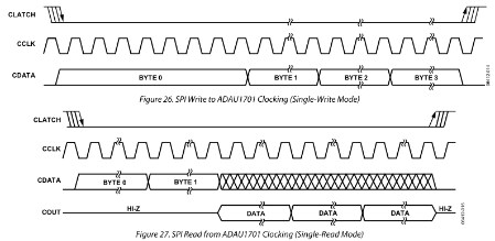
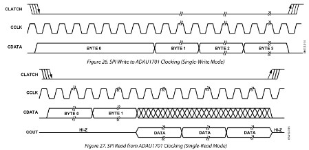
You only have to pull the CLATCH low three times to put the ADAU1701 into SPI mode. This only needs to be done once; at that point, the IC will remain in SPI mode until it is reset or powered-down. The four lines in this diagram only indicate that the CLATCH signal can rise/fall at any point in the illustrated time there.
The maximum SPI CCLK frequency is shown in Table 8 of the ADAU1401A datasheet. The maximum clock speed is 6.25 MHz.
ok, thank You!
Now I know that the problem is not in the Latching Signal!
I will verify (again) all the other digital signals between uC and DSP
Please log in to reply.