Generic Gain Envelope
Hello,
I'd like to use the Endless loop algorithm (ADI Algorithms/Envelopes/One Sweep w/Reset/Endless Loop,
I'd like to configure the slope and the timing in my fw.
In the include file I find and I immagine
1. MOD_ENVCH1_ALG0_GAINTIMING0 --> time in ticks where the gain start to change
2. MOD_ENVCH1_ALG0_GAINS0_VALUE --> the gain descrement ????? HOW TO COMPUTE THIS VALUE???
3. MOD_ENVCH1_ALG0_STARTINGGAIN_VALUE --> the initial GAIN
4. MOD_ENVCH1_ALG0_LOWESTALLOWEDGAIN_VALUE ---> the lowest gain ..
I need to create a gain evelope starting from 0db and after a number of ms (a parameter) I need to reach -20dB
Anyone know how to calculate the parameter gain step ?
For your reference
I found the formula for the GAIN PARAMETER:
Starting from the dB domain the relation is:
dB(t) = (deltaDB / DeltaTicks) * t (where (t) is the current ticks from 0 to DeltaTicks)
10 ^ (dB(t) / 20) = 10 ^ (DeltaDB/DeltaTicks/20) * 10 ^ t
------------------------------
The coefficent used in the algorithm is : (DeltaDB / 20 / DeltaTicsk)
Example:
Start 0dB end 22dB in 1000 ticks ( for a 48K sampling rate ~20ms)
GAINCOEFF = (0 - 22) / 20 / 1000
Thanks for the answer,
with SigmaStudio everytingh is simple, the program give me a big help during the initial developing stage!
Unfortunately in my firmware I need to modify some DSP program parameters in order to modify the filter coefficient, the gain envelope curve,
the mute clickless decay time and so on....
I have to spend a lot of time when I need to implement the algorithm in my firmware and I need to change a parameter!
It's not always simple to find the formula to use to calculate the algorithm coefficient watching the capture window.
I hope to find better documentation in the future release of SIGMASTUDIO about the algorithm implementation.....
Hi Stefano,
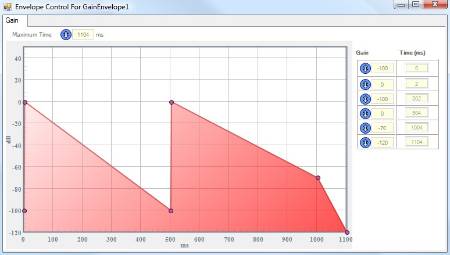
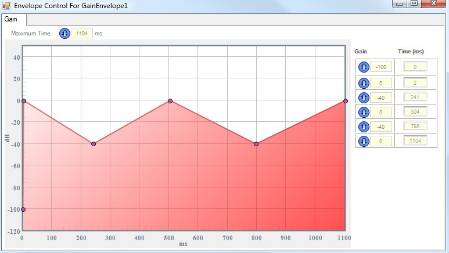
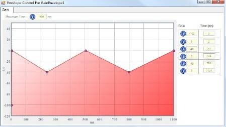
Like many things in SigmaStudio, the generic gain envelope algorithms are best configured in their GUIs. The GUI for these algorithms isn't immediately intuitive: simply click the blue gain envelope icon to access it.
Set the envelope as you wish.
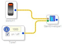
Now connect your input signal to the blue pin and a logic control signal (28.0 format) to the red pin.
When the switch is off, the output will be zero. When the switch toggles on, the gain envelope will start. For the single-shot version of the algorithm, the gain envelope will execute once. For the looping version, it will loop indefinitely. When you turn the logic switch off again, the output will go to zero.
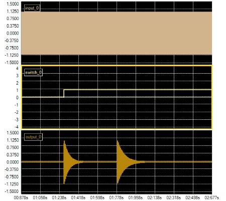
Here's a scope shot of the single-shot version:
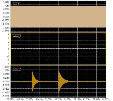
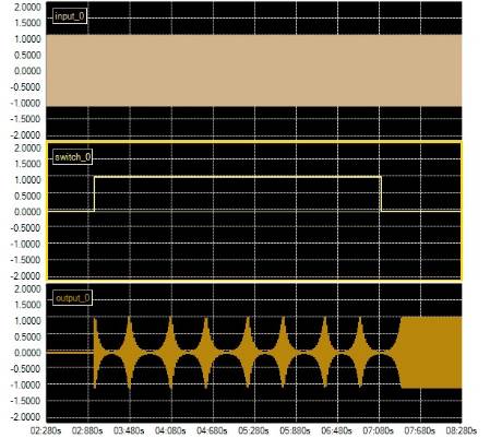
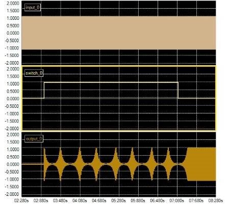
Here's an example with the looping version:
Note that the output remains off until the switch is first toggled. Then, the gain envelope loops as long as the switch is on. Finally, when the switch is turned off, the gain envelope completes its last loop and holds the last value (in this case, 0 dB).
To see how to edit all of these parameters in your firmware, simply use the capture window or parameters window.
C.2.Capture Window
C.3.Parameters Window


I understand and agree with your comment. Some parameters can be calculated easily using formulas from the help file or built-in software tools (for example, 2nd order filter coefficients).
However, other parameters are not derived at all in the help file, and you may need to plug in a few test point values in order to determine the relationship between the parameter value and the value stored in RAM.
I will stress to the software team that these derivation formulas should be published in the help file in future revisions.
I have some trouble with the endless gain envelope:
For test I use a sinewave generator 1KHz in input to the gain enveloper.
In my algorithm I need to start with a constant envelope, when a event occurs I need to set the gain envelope with a specific slope
in order to obtain a pulsed (with varaible period and duty) signal.
my params :
0ms: 0dB
1ms : -1dB
20ms : -20db
40ms: -100db
XXms -100db
XX+40: -40db
XX+59: -20db
XX+60: -1db
XX+61: 0db
XX+NNms 0dB
where NN is the period of envelope and XX the "duty cycle"
To generate the constant envelope, after the initialization I set the switch in order to start the gain envelope as you suggested, after some milliseconds I switch off the gain envelope.
The resut who I obtain is an output with a gain of about 40db less that what I'm thinking to see.
If I test the firmware step to step the output reach the correct value.
Have I to wait a complete envelope period before to stop the gain envelope module?
Could you suggest me a different way to perform this task?
Please log in to reply.