1701 Performance scaling with sample frequency
Most data for the 1701 are specified at 48 kHz. However the chip can be used at many other sampling frequencies.
One detail mentioned in the data sheet is the input voltage range that must be considered but how do other specifications change?
I would like to know for example noise, distortion, anti aliasing filters in/out, execution capacity.
Are there any other issues with using higher sampling frequencies with the 1701?
Audio Signal Processors
SigmaDSP Audio Processors
adau1701
Hello seeker,
The ADAU1701's master clock frequency can be scaled with minimal adverse effects. The analog portions of the device were designed so that they can be frequency scaled by a certain extent and still perform as advertised. The ADC's input resistors are the only hardware components that need to change as a result.
However, the ADAU1701 was only designed to run at 44.1/48/96/192 kHz sample rates, and min/max specifications in our datasheets are only guaranteed for the test conditions listed. In the case of the ADAU1701, the spec tables all show values measured (and guaranteed) at MCLK = 12.288 MHz, fS = 48 kHz. Using a different MCLK value technically voids that guarantee, but in practice the noise, distiortion, and other analog performance specs should remain essentially the same.
The PLL input frequency range is limited, and if you vary the MCLK too much, it could cause the PLL to lose lock. Since the PLL was only designed for inputs +/- 20% of nominal (this is listed in the datasheet spec table), you need to keep it in that range in order to guarantee functionality.
Best Regards,
Brett
Brett,
Thanks for the clarifications. I hope you can answer a few more questions regarding the performance.
I've continued to test the evaluation board, the small one.
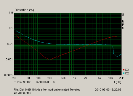
The first issue I came across was high 3rd order distortion at higher frequencies. I saw that the evaluation board had different output passive filter (56 ohms + 56 nF) than the recommendation in the datasheet (560 ohms + 5.6 nF).
After changing these components the distortion at higher frequencies became lower, but not low. Will the distortion be according to spec with an active output filter?
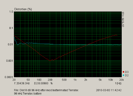
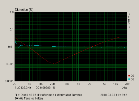
The measured distortion at 48 kHz and 96 kHz are included here. The DSP setup is transparent in/out. The level is 0.775VRMS. The evaluation board is battery powered.
(The measurement setup itself gives about 0.001% over entire freq. range.)
I assume that the raised distortion at high frequencies is due to the DAC output circuit (no active buffer but with datasheet component values.) Please comment.
Why is the 3rd order distortion raised at low frequencies? (2nd order also raised at low frequencies but only at 48 kHz sampling)
Regards,
seeker

Brett,
I understand that using the full signal path with ADC and DAC give worse figures but that is the way I plan to use it and therefore the most valid ones for me when doing the evaluation.
The passive output filter on the demoboard with 56 nF is a very high capacitive load and increase the 3rd order harmonic due to limited drive capacity of the DAC output circuit (at least my assumption). The distortion went down by a factor of 3 (at 10 kHz) when changing the capacitor to 5.6 nF.
Do you have distortion figures using active output circuit compared to passive?
Why is distortion increased at lower frequencies?
Regards,
seeker
Hi seeker,
The -90dB THD+N typical spec on the DAC outputs reflects a digital input signal of -1 dBFS on the I2S input ports, which is sent directly to a single DAC and output through an active filter. This value represents a typical value seen on our special test board that is used to verify the devices when they are manufactured.
Your setup is quite different in that you are using an analog input as a source. The ADCs have a typical THD+N performance measurement of -83 dB, which is a bit worse than the DAC side (however, this is typical in audio converters). The analog input you are using is also a little under the -3 dB of full-scale value that we use in testing - which maximizes performance - so the performance you're seeing will be a bit lower as a result, simply due to an increase in the noise floor relative to the signal. The distortion introduced by the ADCs is being passed through the DSP and out on the DACs, where additional distortion is introduced from the DACs themselves. If you are running more than one channel, the distortion will increase slightly as a result.
So, there are many distortion sources that become a factor with a fully analog system and passive output filters. As a result, the performance you'll see is worse than what we see on our test and characterization hardware. With a digital input and active output filters, your performance would increase.
I'm not sure why the 10x scaling factor on the RC LPF is making a difference in your distortion measurement. Because you are scaling the R up and the C down proportionately, the cutoff frequency of the filter remains the same, so I would expect that the performance would remain similar as well. It's possible that varying characteristics of the capacitors could be playing a role, assuming the passives you swapped out are of higher/lower quality than the ones we originally populated, but I'm not sure. If that point is of great concern to you, I can ask the DAC designers for more detailed information.
Hi seeker,
When making THD+N measurements in the audio band, the upper harmonics start to shift out of the audio band when the test tone's frequency is increased. This is why standard measuring procedures involve a 1kHz test tone and brickwall bandlimiting filters at 20Hz and 20kHz (although 22kHz is allowed).
When measuring a 10kHz test tone, only the first harmonic at 20kHz is still in the band, but due to the filters used on the output (whether active or passive), that harmonic will be attenuated. This is why a THD+N measurement with a test tone at 10kHz is not considered to be a valid measurement. In fact, the IEC (International Electrotechnical Commission) says that the upper limit on a valid THD+N measurement should be a 6kHz test tone with the first 5 harmonics (out to 30 kHz) included in the measurement.
Measurements of harmonics outside of the audio band can be useful during development stages because they can reveal other artifacts that indicate high frequency problems, but for test and spec publication, a 1kHz tone measured flat over a 20kHz bandwidth is the norm, and this is the test setup we (and our competitors) use in our datasheet spec table.
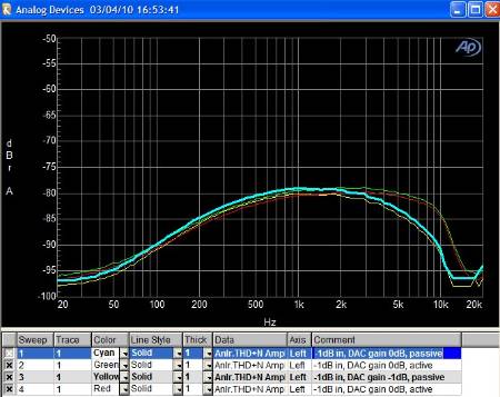
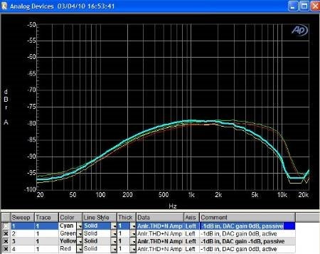
I have included a picture of bandlimited THD+N sweeps across frequency. This was measured on the full analog ADC-DSP-DAC path of the ADAU1701. The dip near the lower frequency range shows that our converters perform a bit better at low frequencies. Across the "important" part of the spectrum, the THD+N is essentially flat at -80dB. Once you hit about 6kHz, you can see the THD+N decreasing because the 5+ harmonics start to shift out of the audio band. The passive filters have a more relaxed roll-off, so they have additional attenuation on the upper harmonics. The active filters have a more sharp corner, so you can see that their THD+N drops off steeper but at a higher frequency. This is more of a sign of frequency response rather than THD+N frequency dependency.
In summary, all audio systems will show frequency-dependent THD+N measurements, so you shouldn't be too concerned about those measurements. Measuring at 1kHz is a good standard for comparing the performance of different devices.
For your reference, I included some quick measurements I made on the evaluation board with active filters enabled. The performance with passive filters was similar. I misplaced those measurements, but I'll post them again when I have time.
DAC-only path
SNR 103dB
THD+N
@1kHz, 0dB -83.7dB
@1kHz, -1dB -89.9dB
@1kHz, -3dB -90.7dB
ADC+DSP+DAC path
SNR 97dB
THD+N
@1kHz, 0dB -80.3dB
@1kHz, -1dB -81.2dB
@1kHz, -3dB -83.1dB
Note that these measurements match what you would expect by looking at our typical values in the datasheet.
I think you're correct about the increased capacitive load causing straining the drive capability at higher frequencies, although I wasn't able to confirm that with the designers yet. I'm guessing that in your test the actual output was being attenuated, which in turn showed up as a lower THD+N. So, this is probably indicative of a sag in the frequency response rather than frequency-dependent THD+N, as explained above.
Hi Brett,
Thanks for publishing your measurements of the THD vs frequency. This was very helpful.
My measurements were done with 96 kHz sampling so that's the reason why I didn't get the attenuation of higher harmonics as you did. I'm not band limiting the output spectrum either. This is intentional since I want to evaluate the circuit.
It was also interesting to see that the performance was not better with active output filters. That really surprised me. The filter type you recommend for the active circuit has a 3rd order bessel slope and together with output buffers should be able to achieve better performance
I'm still a bit puzzled of the higher 3rd order distortion at lower frequencies in my measurements. I don't think this is a problem in real life but I would like to understand why. Maybe there is a difference in test set-up, difference in measurements methods or even a difference in the type of power supply used. I used a 9V battery regulated by a 7805 linear regulator to get 5V to the evaluation board.
When doing noise measurements I can see that there is an increase in noise spectrum towards lower frequencies. Maybe the noise is responsible for the measured increase in distortion.
Regards,
seeker
This question has been closed by the EZ team and is assumed answered.
Please log in to reply.