Designing PCB for ADAU1701 / SigmaStudio questions
Hello everybody
I want to design a new PCB for the ADAU1701 DSP processor. I would like to build it into existing high quality power amplifier. Can anybody give me some advices to create the best possible PCB for the ADAU1701?
The amplifier itself provides 15 volt negative and 15 volt positive for logics and input stage. When using a voltage regulator like a LM78L33 (or something like that) is it possible to connect all the supply connections of the ADAU1701 to this regulator? Or is it better to create a seperate second supply for the digital or analog parts of the ADAU1701? In last case, do i need to seperate the digital from the analog grounds? Do both need ground planes?
I have also 2 questions about programming with SigmaStudio:
Is it possible to create a led level output meter with some leds connected to the GPIO outputs?
And is it possible to make a function that rise up the audio signal slowly when the amplifier/DSP has started up? Just to avoid speaker damage when amplifier turns on with full signal present.
Thank you very much!
Best regards
Audio Signal Processors
SigmaDSP Audio Processors
adau1701
Hello audiodude,
Quite possibly an engineer with more PCB layout experience than myself could provide more specific assistance, yet for now here's some helpful references:
Layout at the DSP: The authoritative guide is: SigmaDSP PCB Layout Best Practices Separate analog and digital ground planes have not proved necessary -- a mixer my company built with six ADAU1701's sharing a lone ground plane works fine. The most important considerations are:
Placing the small bypass caps right at their associated chip pins without intervening vias -- see Custom design with ADAU1701
The crystal and PLL circuitry likewise need "immediate" connections to their pins -- see ADAU1701 /1401 Recommended Crystal Layout
Voltage regulator: In the mixer described above we regulated its main 24V supply down to 3.3V for powering the DSPs. We used a high-frequency (several hundred KHz) switching regulator after discovering that a lower-frequency one created a faint audible whine. For just one ADAU1701 using about 110 mA, you might prefer a linear regulator. Bypass the regulator's input and output pins according to its data sheet.
Power wiring: Think where the power supply and ground currents to/from the power amplifier go. Then make sure that their associated voltage drops in no way add to the DSP's output -- lest these nonlinear currents cause terrible distortion. See Too much THD with MIXER on ADAU1701
Output metering: Definitely possible, although the number of LEDs is limited by the available GPIOs. Search the forum for some references to multiplex schemes. If you do multiplex, be careful where these currents go as well -- we have had problems with multiplexed LEDs adding audible "buzz."
Startup delay: A ramping gain at startup is quite possible. If your power amplifier has an enable input, you could also provide a delayed enable via GPIO.
Hope this helps!
Best regards,
Bob
Hello Bob,
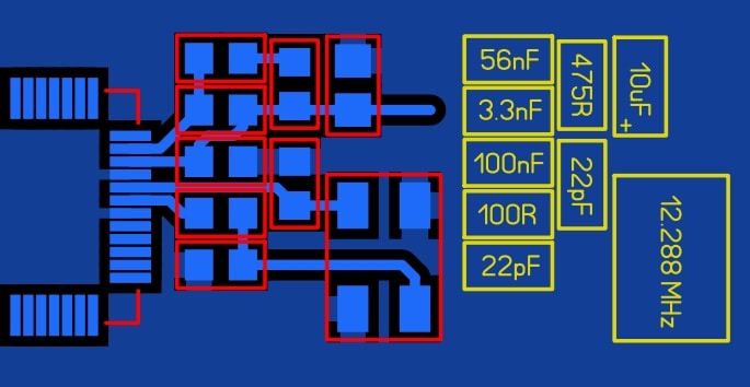
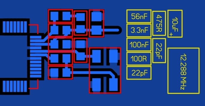
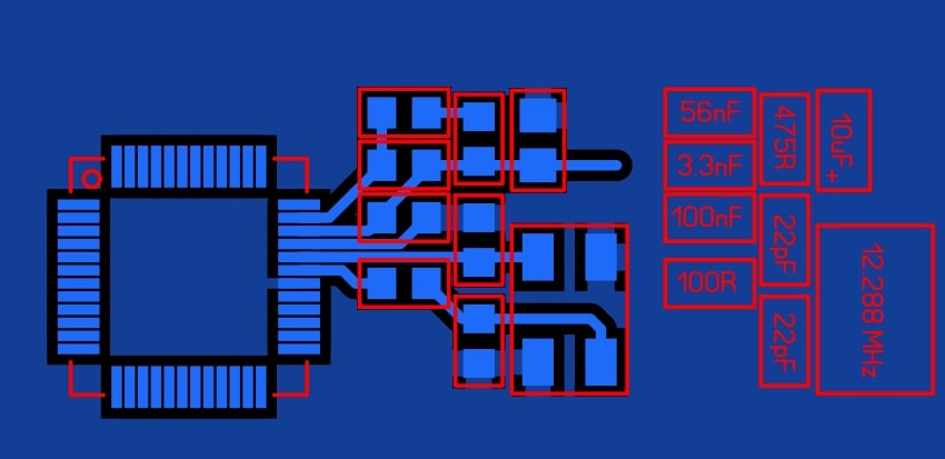
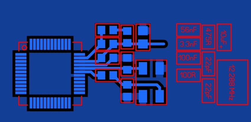
Thank you very much for your helpfull information! With this information in mind, i'm started to design a new PCB for the ADAU1701. In the pictures below i show you what i have designed for the PLL and the crystal. The first picture is with silkscreen, the second without. On the right side you will find the values for the used components. Can you tell me if this design is ok?
Also, can the PGND be connected to a ground plane, just like i did in my design?
With silkscreen:
\
And without silkscreen:
Please let me know. Thank you very much for helping Bob!
Best regards!
Hello AudioDude,
The 100nf cap needs to be across the PVDD and PGND pins. PGND should not come from the ground fill under the part. It needs to go "by" the 100nf cap on its way to the ground plane. It is important for the decoupling on those pins to be really local to each other.
After that, the way you do all the rest of the power and ground is important. Make sure you run the traces from the power and ground to the bypass caps first then to the power and ground layers.
I assume you have at least a four layer PCB with a full ground plane and a power plane right?
Dave T
Hello Dave,
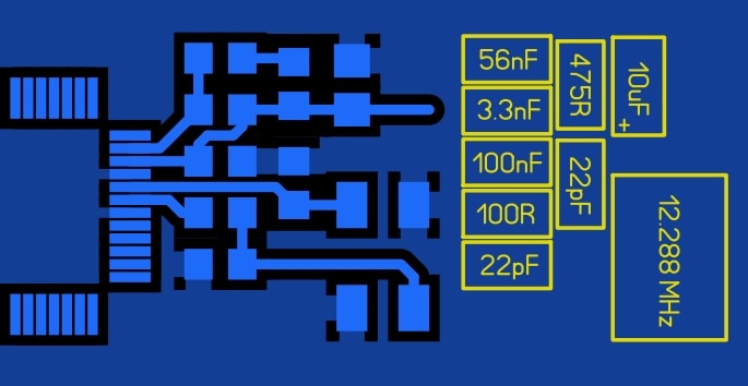
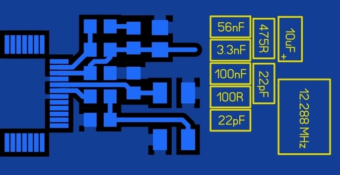
Thank you for your answer. Do you mean something like this for the PGND pin?
If it's ok, i'm gonna try to do the same with all the power en other ground traces.
I do not know for sure if my PCB manufacterer has the capabilities to make a 4 layer PCB. I shall ask them.
Hello AudioDude,
Yes, that looks good.
Any PCB manufacturer can build multi-layer boards. I would be shocked if they were not able to. You have to use ground and power planes otherwise the trace impedance is undefined and will cause a lot of issues with the digital signal transmissions.
Dave T
Please log in to reply.