the PLL of bf533
I design a BF533SBBCZ400 board, when i test it by ADSP 5.0, i found that:
1.when i want to make the PLL frequency multiplication effective. Firstly,i have to switch to active mode,
and then i have to switch to FULL_ON mode.
2.After executing the program under the ACTIVE mode, it must be recompiled and loaded by the emulator to make the previous settings take effect.
After that,the core clock will change.
When i test it , i find that the total current consumption due to the internal core circuitry is too small . For example, in an application with VDDINT at 1.2 V and a high-performance Blackfin processor at a TJ of +25oC, the corresponding IDDINT for the VDDINT power domain would be approximately 75 mA. Bf533 processor is not working properly.
I think it may be the hardware problem, but i don't know how to find it.
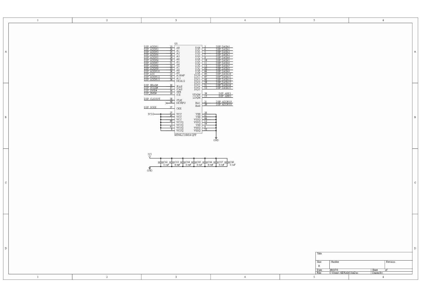
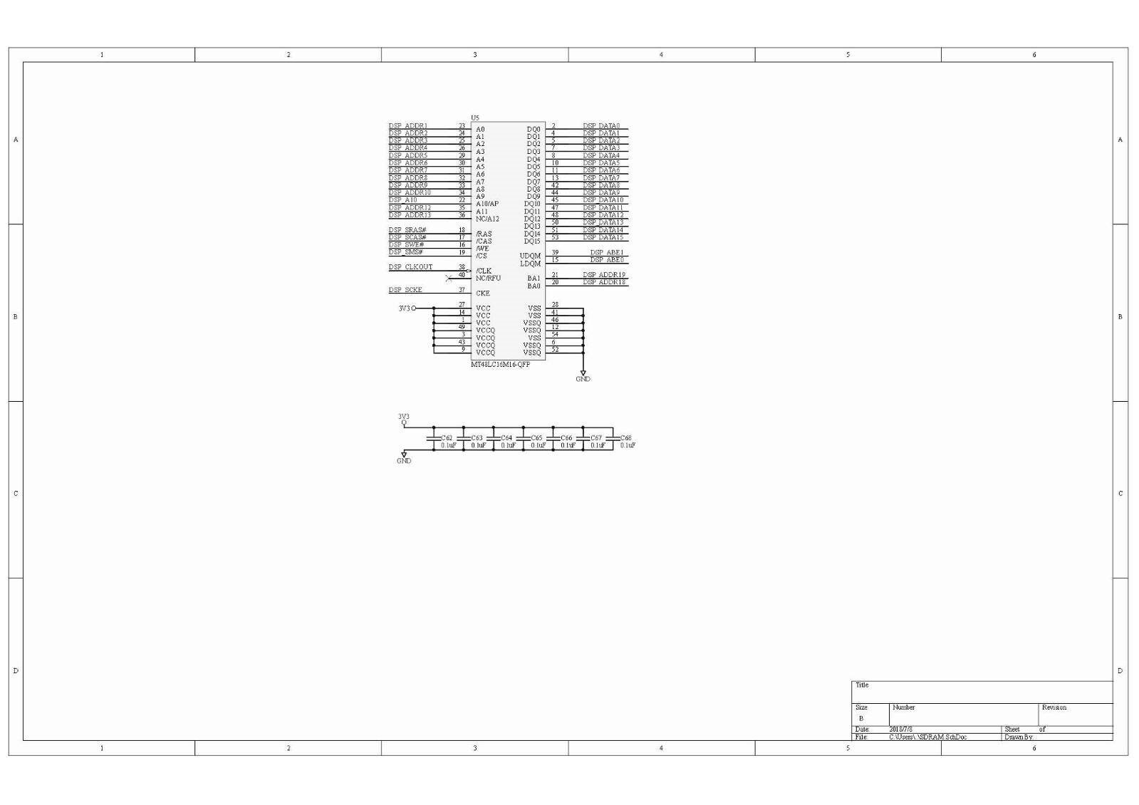
The following is the schematic part of my board:
The following is the PCB part of my board:
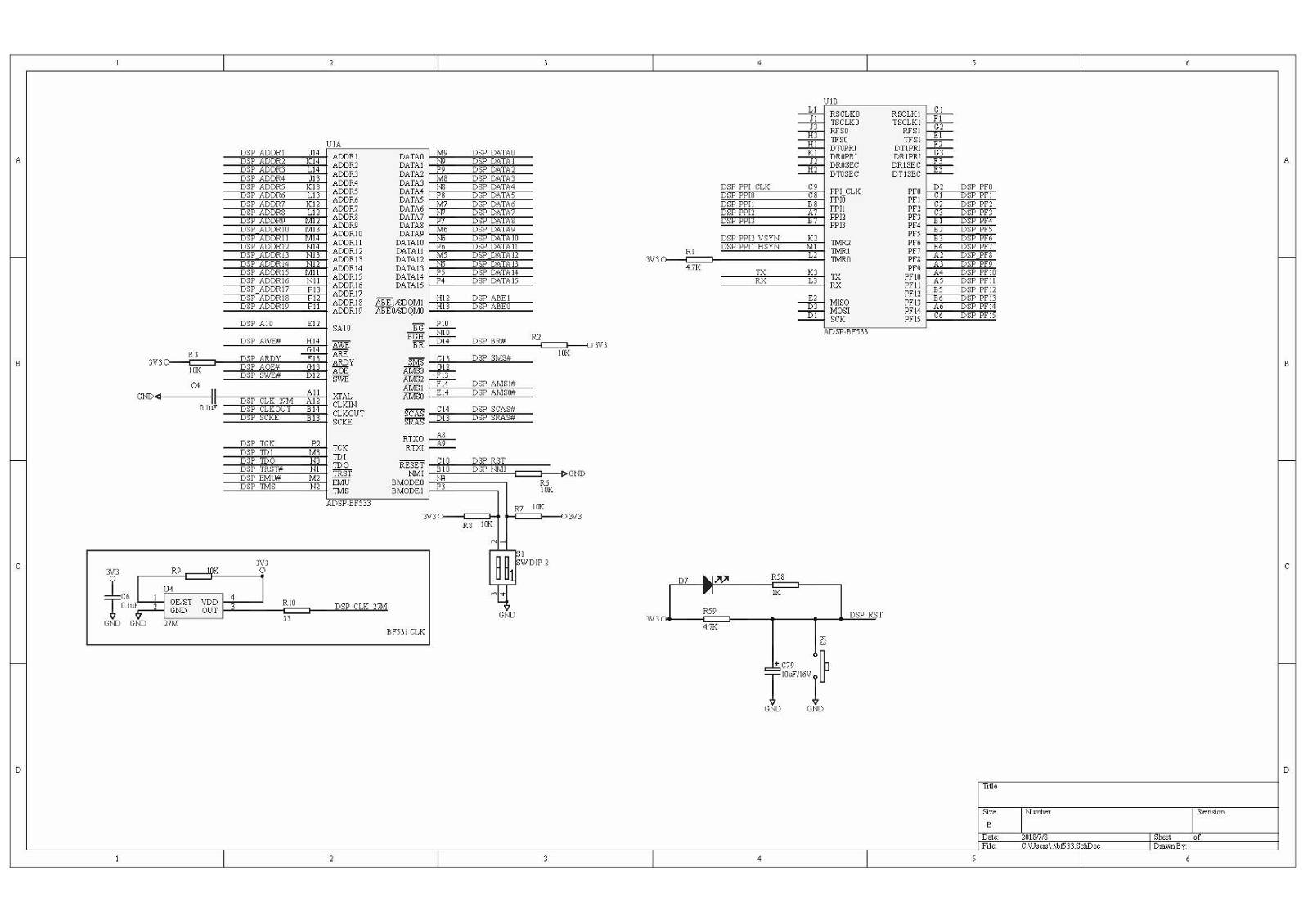
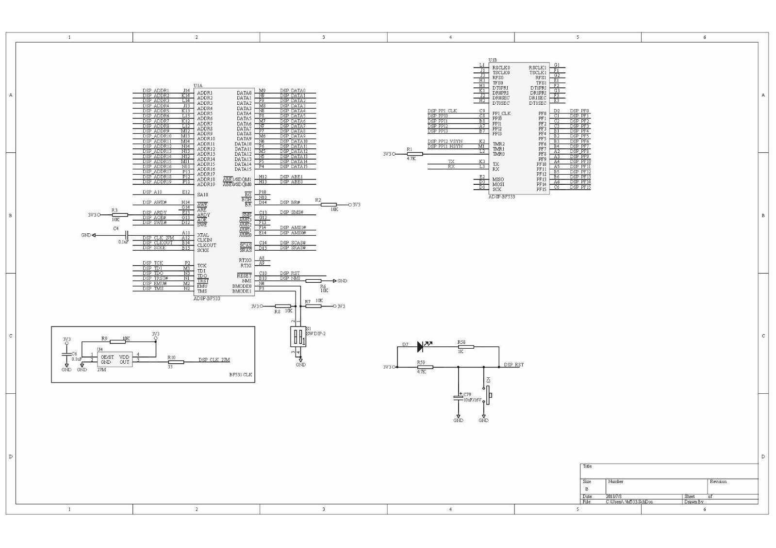
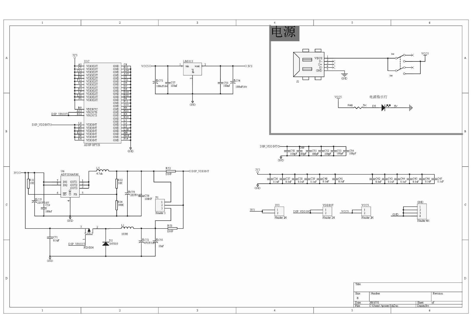
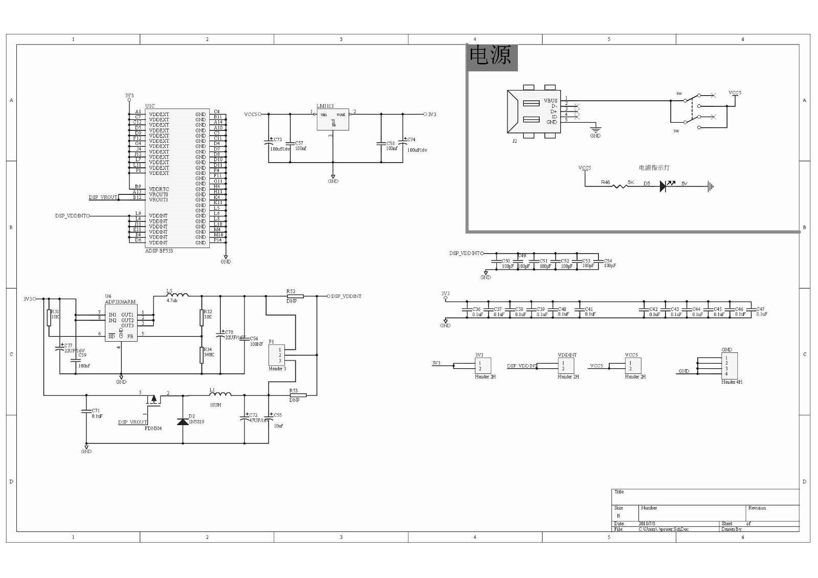
Hello,
We have an evaluation kit for BF533 processor, EVAL-BF533-EZLITE Evaluation Board | Analog Devices
You can cross verify your schematics with the one available in the BF533 evaluation kit. See the manual given below.
Board Design Database of this kit can be downloaded here. This design package contains the electronic information for the design, layout, fabrication and assembly of the EZ-KIT Lite.
Hope this helps.
Best Regards,
Jithul
In addition, you would find the example codes (including PLL configuration) for BF533 Ez-Kit in the VisualDSP++ 5.1.2 installation folder, the default path is given below
C:\Program Files (x86)\Analog Devices\VisualDSP 5.1.2\Blackfin\Examples\ADSP-BF533 EZ-KIT Lite
Best Regards,
Jithul
I read the data sheet of bf533, it said that the RTXI pin should be pulled low when not used.
If the real time clock is not used and i didn't pull the RTXI and RTXO ports low.
Will the above situation affect my core clock?
Please log in to reply.