ADAU1451 self-boot failure with I2C ROM
Hello,
I have a design where an ADAU1451 attempts to boot from I2C ROM at power-up. Self-boot pin is always high and 1451 reset pin is controlled by a connected MCU (Kinetis K22).
Monitoring the boot shows that the 1451 is successfully reading the self-boot ROM header (16 bytes). After 5 ms the SDA pin goes low and stays low while the SCL pin remains high. Resetting the ADAU1451 causes the SDA pin to be released and the pin is pulled high again, but self-boot is not re-attempted until after a power cycle of the device. Therefore it is my conclusion that the 1451 is holding the SDA pin low as the only other device on the I2C buss is the slave self-boot ROM. The slave ROM is fully accessible (read and write) from test equipment temporarily connected to the I2C buss for testing.
The ADAU1451 has the slave port connected to an MCU (Kinetis K22) and I can read the PANIC_FLAG (0xF427) and PANIC_CODE (0xF428) registers. I also read the PLL_LOCK (0xF004) which is always 0x0001. Recycling the power repeatedly, always returns PLL_LOCK = 0x0001 and randomly returns PANIC_FLAG = 0x0001 with a single bit set in PANIC_CODE such as 0x0080, 0x0040, etc. However I also get both PANIC_FLAG and PANIC_CODE == 0x0000 but the symptoms remain the same regardless of these codes. My conclusion is that these panic codes are not the cause of the boot to not proceed beyond the ROM header.
The same board, modified to support an SPI ROMn has no problems self-booting from SPI ROMs. For reasons that are beyond the scope of this posting, I2C is required for this particular design, so converting it to SPI is not an option.
I am out of ideas of how to get I2C self-boot ROM to work with ADAU1451. Any thoughts? Thank you kindly.
Audio Signal Processors
adau1451
SigmaDSP Audio Processors
Hello jwhitlatch,
Thanks for some good analysis and lots of good info for me to begin helping you with. Thumbs up!
I should first say that we have many customers, many in automotive applications, that are using I2C for booting with no issues. So the firmware built into the part is validated and has been tested many years ago. So it is not very likely that we are running into a previously unknown bug causing your issues. So let's try to figure out what is going wrong.
Where should I start?... The Panic codes you are seeing are not significant as you have noted. These codes result mostly from reading and pre-fetching uninitialized memory and that happens often when booting up. These features are not to be used for booting up. Generally, if you use the panic codes it is cleared and started once the program is up and running in the DSP. There is one exception. If you read register 0xF433 after you attempt to boot, it may hold a code that is a clue. The selfboot firmware makes three attempts to boot up. If these fail then it will place the value 0xBABE into this register. This will give us a clue that it completed the boot attempt three times. I am guessing you are not getting that far.
For selfboot to be initiated, there are three conditions required. Well, two plus an option. Selfboot pin has to be pulled high and the reset has to have an edge transition from low to high. The option is pin SS_M/MP0 pin has to be pulled low for the I2C bootup as opposed to SPI bootup. So I am assuming this is set properly in your case?
I am wondering a little bit about the contents of the header. The first 16 bytes hold the PLL settings and a couple of other settings like the I2C speed settings. I am wondering if these are corrupted or simply incorrect? Can you attach your hex file? Or show a screenshot of the beginning of that file?
I appears the PLL is locked. It is probably a good thing for me to have a quick look at your schematic of components around the DSP.
What are you using for an MCLK source? What frequency?
Let's start here. I have a meeting in a minute so I need to stop at this point.
Dave T
Hello Dave T,
Thank you kindly for helping to investigate my issue. I am sure it is something silly I am doing or not doing that I should. I am happy to share schematic snips with you privately, not in a public forum.
I do not believe it is getting beyond the header of the first attempt. So, I added retrieving SOFTWARE_VALUE_0 and for good measure SOFTWARE_VALUE_1 and both of these are always 0x0000.
Enabling CODEC MRCLK
PANIC_FLAG = 0001
PANIC_CODE = 0010
SOFTWARE_VALUE_0 = 0000
SOFTWARE_VALUE_1 = 0000
PLL Lock = 0001
Regarding the two required and one optional conditions:
SELFBOOT pin 34 goes to our K22 MCU GPIO with 4K99 pull-up resistor to 3V3 rail.
/RESET pin 24 has 104 cap to ground, goes thru 10R to K22 MCU GPIO with 4K99 pull-up resistor to 3V3 rail.
SS_M/MP0 pin 26 goes through 10K pull-down resistor to logic ground.
Looking at the reset/self-boot timing at power up, the top trace is SDA, second from top is SCL, third from top is the 1451 reset pin and the bottom trace is the clean-boot pin. Reset is pulled high for 0.18ms while the K22 initializes GPIO pins and sets this pin to reset. The K22 finishes it's initialization and then releases the reset pin.
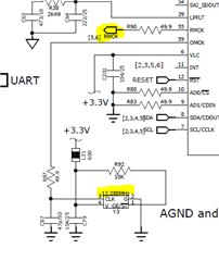
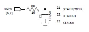
The SCL clocking during self-boot is measured at 38KHz. You also asked about our MCLK source. This is generated by our CODEC (CS42526) from a 12.288 MHz clock source oscillator. The recovered master clock RMCK is basically a buffered copy of the 12.288 MHz oscillator that drives the 1451 and other devices that need it.
Detail of the connection to ADAU1451:
So, hopefully I have provided all the answers that you have requested. Many thanks for your assistance.


Hello Dave,
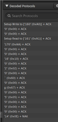
My apologies, I neglected to provide the contents of the header as read from the ROM during self-boot as displayed in the logic analyzer. The byte sequence in case you are unable to read this image:
0xAA, 0x00, 0x00, 0x10, 0x00, 0x02, 0x00, 0x60, 0x00, 0x67, 0x00, 0x05, 0x00, 0x00, 0x00, 0x0e
Hi Dave,
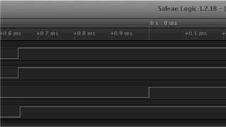
I tried removing the "glitch" in the reset pin just in case that was confusing things. So now self-boot goes high at power-up and the low-to-high transition on the reset pin is 0.34ms later and then it stays high. This apparently had no effect on the symptoms.
Hello jwhitlatch,
Thanks for the info.
There are a couple of things that caught my attention. The first is the cap ,C3, on the MCLK input. I think this is a bad idea. All the simulations I have ever done for Signal Integrity show this to cause more problems than it solves. Keep the serial resistance there. It might be good to increase the value but that would take more analysis. If the MCLK is flaky the PLL might be locking then losing lock and it depends on when you poll it you might not see that.
Internally, there are some conditions that need to be met but from what you have explained I don't see an issue. The power rails should be stable long before you release the reset.
I don't think there is an issue with the reset going up quickly then being pulled down again. It is a good 5ms afterwards so that should be fine.
Check to see if the 10K pull down resistor on the SS line is enough to pull it low. It should be but verify that it is well below the 0.3 x IOVDD voltage point for a logic low.
The fact that you are reading zeros in the Software Value registers means the selfboot is not completing with a failure. So I am suspecting the PLL and the MCLK. The MCLK should appear before you release the reset pin. The rest of the timing will be handled automatically by the selfboot firmware so not much else for me to ask about...
I will look at your header contents and think about this some more. Meanwhile, I will let you do some of these other tests.
Dave T
Thanks Dave,
I am having the C3 104 cap removed and the 10K pull-down we will make 4K7 or so. Without these changes I took the liberty to polling the PLL registers:
PLL_CTRL0 (0xf000) = 0x0060
PLL_CTRL1 (0xf001) = 0x0002
PLL_CLK_SRC (0xf002) = 0x0001
PLL_ENABLE (0xf003) = 0x0001
PLL_LOCK (0xf004) = 0x0001
MCLK_OUT (0xf005) = 0x0005
PLL_WATCHDOG (0xf006) = 0x0001
We will also check the power rail stability at the time of the reset being released in the mean time. Once I have these changes in hand I will retest and let you know what I find.
Hello Dave,
Ok, we definitely have a problem where MCLK is missing when DSP comes out of reset. Pretty classic stupid human trick of generating the clock from a CODEC that has to be initialized to generate the clock, but on the same reset net as the DSP. Doh… We are sorting that out and will get the MCLK ahead of releasing reset on the ADAU1451 and let you know how we are getting on. Thanks for your patience.
Hello Dave,
After all that we are still right where we started with one change. MCLK is starting well before the DSP is released from reset now. Unfortunately, the same sequence is repeated where the ROM header is read and 1.4ms later SDA goes low and stays low locking the I2C buss. The only thing that seems to have changed is resetting the DSP after a failed self-boot does try again to self-boot, but it as well fails in exactly the same way. Oh well... Thank you for your continued assistance.
Hello jwhitlatch,
Thanks for your patience! It is difficult to figure out problems with the hardware right in front of you never mind remotely! We are making progress in that we slowly are checking off possible causes.
So are there now values in the Software Error Values registers?
OK, So now let's focus on the hex file contents. I just looked at the header info and it is quite a bit different from a program file that I have. The difference is with the last four bytes which are the EEPROM speed configuration. So this seems like it can be relevant to the issue you are seeing.
You have 0x00, 0x00, 0x00, 0x0E
I have 0x00, 0x9D, 0x2F,0x60. I am pretty sure the program I used to generate this file is set for a 100kHz EEPROM speed. You will not be able to just change these bytes because there is a checksum for the hex file. You could find the last eight bytes of the hex file and change the checksum to zero, this disables the checksum feature. But you have to be able to identify the last eight bytes for certain. I think it will be simpler to do one of two things.
1) Check to see what you configured for the EEPROM speed? 400kHz will be the max for this part. 1MHz is not supported. There is more to this topic we can discuss if this is an issue for you.
2) I will attach my hex file that you can load into the EEPROM using your tools? Are they capable of doing this? You cannot go through the DSP.
Note: I had to zip the file because our new web interface will not upload a hex file directly.
The rest of your header is exactly the same as my hex file. So the PLL config is good for a 12.288MHz MCLK.
E2Prom.zip
Dave T
Hi Dave,
This appears to be the reason that the DSP fails to boot, or at least I can say that it will boot your image. I created a DSP audio pass-thru simple image with the correct settings and now self-boot is able to load it.
So, thanks to you this particular issue appears to be resolved.
If I may be so bold as to ask a related question I would appreciate your insights.
1. Does the DSP master port operate correctly in a multiple master environment?
2. If not, is that limited to self-boot time or also after the image boots?
The situation is the need to be able to self-boot but also update the self-boot ROM image in the field from the MCU. The issue is both DSP and MCU want to be master on the buss. Now that the boot is working I connected the MCU and DSP to the I2C buss and the MCU is unable to communicate once the self-boot has commenced. I will dig into this separately and raise additional issues here as needed, but if you could give me your initial thoughts on this, that would be appreciated.
You get the gold star award, sir. Thank you for all your assistance.

Hello jwhitlatch,
Glad we got through this! It was a little tricky but you gave me really great data to work with! That is a huge help!
The DSP master port does not operate in a multi-master bus. Since you only have the DSP and the MCU that want to be masters, you only have to be sure that the MCU is not trying to communicate while the DSP is booting. After it completes booting it does not care what is going on with the bus.
However, if you do some runtime access then it can be a problem.
So it seems like your MCU has access to both the Slave I2C ports and the master I2C ports on the DSP?
I suppose you either have two comms ports on your MCU or have a switch for routing to either?
In that case if you have access to the master I2C bus that the EEPROM is sitting on, then you can just directly write to the EEPROM without going through the DSP. This is much simpler. So you write the new image and then reset the DSP and it will boot it up.
So if I anticipate your next question, How do you know when the Selfboot has completed? There is no register that is made for this so you have to setup something. There are a few ways to do this.
One way is to setup a GPIO pin on the DSP that is connected back to an MCU GPIO pin. Then setup the GPIO output to be driven by a DC cell set to zero. The GPIO pins start up as inputs so you can put in a weak pull-up to be certain that it will float high. Then when the program loads in it will stay high until it starts running. Then it will go low. This will be your signal that Selfboot is complete.
You could also just wait a set amount of time.
Now, you could just read the GPIO value register. but this means the MCU will have to be polling the DSP on the slave port. You should have provisions for this I assume.
Some users will setup a heartbeat of some sort out of the DSP. You can do that but it uses up a few MIPS. You can also do a calculation like taking two DC cells and adding them. Then send that to a Readback cell and read that cell. It will not contain the correct number until the program has run through at least one frame. This would not require any GPIO. Then it can also serve as a way to know the software revision if you like.
In hindsight, this is one register that would have been handy, a selfboot result register. We did half of it by having an error value but there should have been a "boot successful" value. This part was a huge leap from the previous SigmaDSP by having two ports. With the older parts you cannot poll the part while it is booting because there is only one port. Anyhow, I digress.
Have a Great Day!
Dave T
Good information Dave.
My MCU can initialize the shared I2C bus while holding the DSP in reset and write the ROM, but not if the DSP is not in reset. My experience is that after the self-boot, the DSP pulls both SDA and SDL low, effectively locking the buss and preventing any other master (including my MCU) from doing anything on the buss. Does this not match your experience? This approach would allow me to write the new ROM contents, but after boot is complete, the MCU can no longer communicate with any other slave on the buss.
I suppose I could try to set up the DSP myself over it's slave port and not use any self-boot ROM at all. The datasheet has an example table of the myriad of register settings and SigmaStudio produces the program, DM0 and DM1 file in various formats, but it seems a bit tedius and I fear whatever that table does not tell me. :) Perhaps that is what the generated function default_download_IC_1 is for, eh?
Any advice on the best approach for this in-field firmware upgrade scenario?
Hi Dave,
Thanks again for all your help. I thought I would let you know what I ended up with for a final solution. Rather than put a self-boot ROM on the DSP, I have decided to put it on the MCU and eliminate any multiple-master issues on the buss. While I did get the I2C self-boot working, there were some issues with the MCU drivers forcing re-initialization of the drivers after the self-boot completed. I just was not satisfied with the design, so the MCU will be a single master for the ROM and the DSP is booted by the MCU over the slave control port. This is working nicely and eliminates the multiple master set-up and the associated fiddly issues where neither device truly supports multiple masters completely.
Again, thanks for being a rock star and helping me through this set of issues.
Please log in to reply.