ADAU1452 multi output selector routine request help
How to use gear switches to control multiple output selectors?
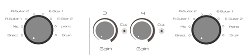
Using GPIO (MP9, MP8) IO as control, how to achieve 1-8 preset EQ channel switching, and whether POP voice can be avoided during switching?
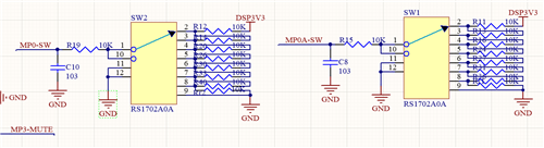
The voltage dividers of gear switches are 2.88V, 2.475V, 2.063V, 1.65V, 1.238V, 0825V and 0.413V, respectively.
Hello jamesli,
Sorry for the delay in responded.
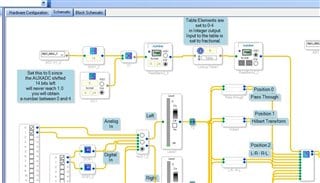
I think the easiest way is to use an AUXADC and scale the output and feed it to a table. Just be certain that the control input to the De-MUX never exceeds the number of outputs-1. Most of these cells are not limit protected so this means you would be stepping on memory locations that are used for other objects.
In your hardware schematic I see the switch is not starting from 3V3 but from one step down the resistor ladder. So you might have to make a slight adjustment to get the levels to work properly. So you have 8 positions on your switch but the divider has 9 positions. So you might have to set it for 9 in your program so it divides the expected voltage range of the AUXADC properly. Then I would either put in a limiter on the control input because if the switch is a break before make then for a millisecond or so you might float up to 3V3. Another way to do it is to have a 9th output of the MUX going to nowhere. This way if it is ever selected it would be a safe setting.
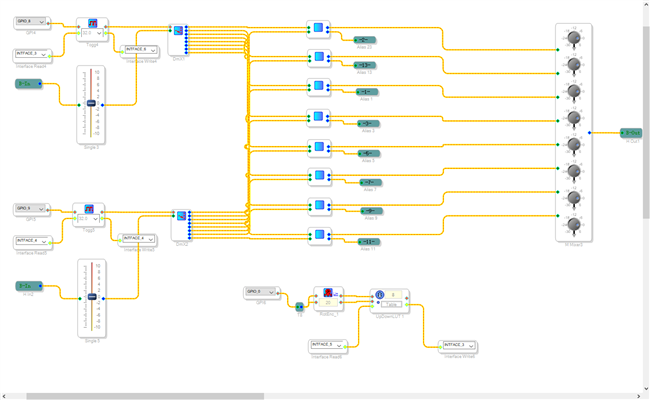
Here is a screenshot of my example program and I will attach the project as well.
Note that this project uses a multiplexer rather than a demultiplexer. Obviously, they will work in the same way with regards to the control of the switch.
Thanks,
Dave T
5165.ADAU1452REVB Headphone Spatial Widening-with external MUX.zip
Hello james,
Glad you searched and found the answer. There is a lot on this forum. I suggest you should follow KJBob. He has so many different posts that shows a number of creative ways to use SigmaStudio. You should find some inspiration there.
Thanks,
Dave T
Please log in to reply.