Still having trouble with rotary encoder volume control
Hi,
Dave, I followed your suggestion and looked at your post from a while ago, https://ez.analog.com/dsp/sigmadsp/f/q-a/120659/adau-1701-rotary-encoder.
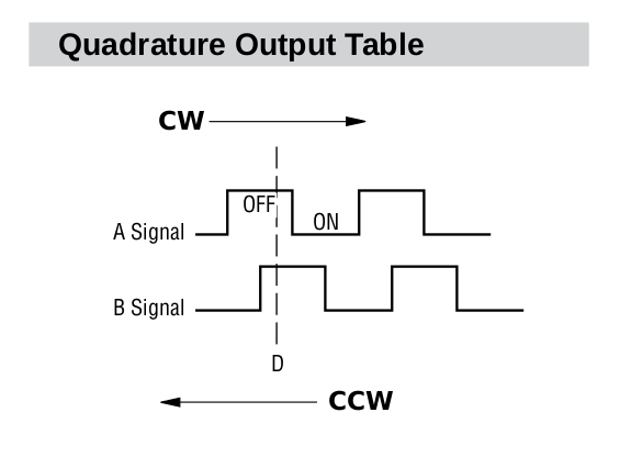
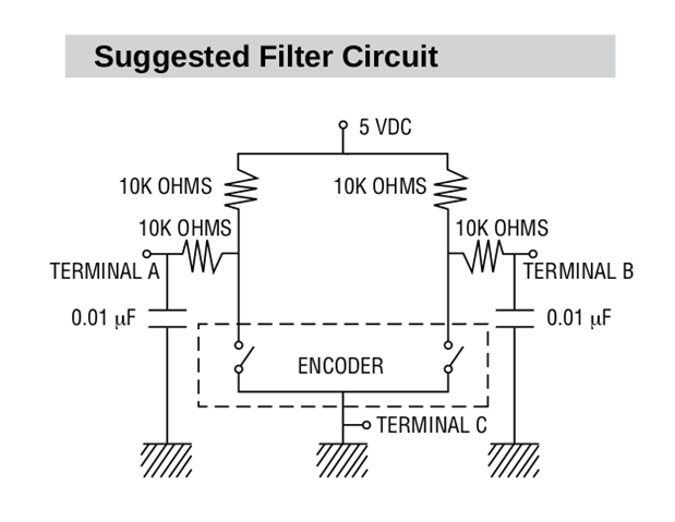
I'm using a Bourns series PEC11R rotary encoder — https://www.bourns.com/docs/Product-Datasheets/PEC11R.pdf. From what I can see, on the figure Quadrature Output Table on the first page,
and Suggested Filter Circuit on second page, it seems like this encoder is a "Type 1" (using the informal terminology you proposed in your post), which you say is the behaviour that the SigmaStudio rotary volume control expects. I am using the suggested filter circuit, and connecting to M12 and M13 of the ADAU1466 using the evaluation board:
I did confirm with an oscilloscope that the waveforms are consistent with the Quadrature Output Table figure in the datasheet. Does the rotary volume control imposes any timing requirements on the pulses? That was the only "weird" detail I could notice — when moving a single click, I would see the two pulses, with overlap as expected, but some times one pulse could be something like 10 or 20 times longer than the other one (for example, maybe signal A goes to 0 at t = 0, then signal B goes to 0 at t = 20 ms, signal A returns to 1 at t = 20.5 ms, and signal B returns to 1 at t = 21 ms, or strange timings like that)
Notice that I do get audio if I set a value ≠ 0 as the first entry of the table (the volume control seems to be set at the first table entry upon start, and since the control never reacts to the rotary device, the actual volume never changes).
Any ideas?
Thanks,
Carlos
--
Audio Signal Processors
rotary encoder
sigmastudio
SigmaDSP Audio Processors
evaluation_board
adau1466
Show More
Hello Carlos,
The Bourns diagram is not clear where the next detent is? It only shows one detent. Are both A and B always off at every detent?
Have you put in Readback cells on the GPIO inputs to see if they ever change? Turn the control very slowly so that you should be able to see the GPIO change. Set the Readback for continuous read so you can see the change without clicking on the button.
You need to determine if the pulses are actually reaching the core. Which DSP are you using? I think you had mentioned this in another post.
Dave T
Hello Carlos,
After posting my earlier response, I ran into this post from 2017. I may have been looking too hard for this problem when I had solved this earlier. This is where using Readbacks help because you would see that the polarity is wrong.
Look at my answer to this old post and try it. This may be the answer.
https://ez.analog.com/dsp/sigmadsp/f/q-a/64434/adau1452-rotary-encoder-not-working/362049#362049
Gee, I should go back and search my old posts from time to time. :)
Dave T
Please log in to reply.