ADAU1701 Strange Input/Output behaviour
Hello,
I'm using the DAC of the ADAU1701. As soon as I place the "Input" block in SigmaStudio and upload the Program the Audio from the DAC automatically gets forwarded to the ADC. And when "Master Mode" is checked one of the two DAC inputs automatically gets routed to all digital outputs. this behaviour can only be stopped by deleting the "Input" Block.
I hope you have some idea what causes this strange behaviour.
Audio Signal Processors
sigmastudio
SigmaDSP Audio Processors
adau1701
Hello Sachr,
I am trying to understand what you are trying to do? Can you zip your project file and attach it?
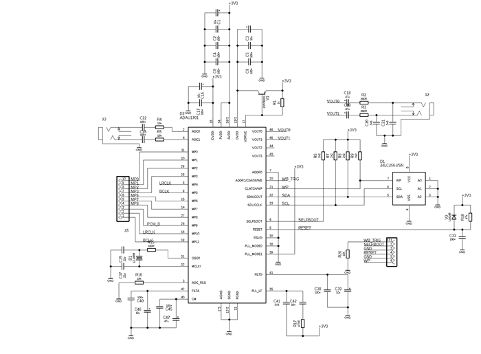
Also, detail what you are doing in hardware for the serial ports. Your circuit schematic might be helpful.
Dave T
Hello Dave,
Here you can see the relevant part of the schematic. A class d amp is connected via I2S (specifically MP9, here called PCM_D). For now all I am trying to do is relay the stereo audio from the two ADCs to I2S on MP9. As to the project there's not much to it: At the moment I place the input block in sigma studio the ADC input gets routed to the outputs, without even one output block being placed nor connected. I am uploading via MCU with the exported system files and modified SigmaStudioFW.h which brings me to believe that my problem could come from the upload code.
Hello Sachr,
I am wondering whether your MCU is properly uploading the program code to the DSP. I see that you have a header for MP0 on your board. Here is something you can do to test whether the program is running:
Configure MP0 as an input with pullup (this should be the default).
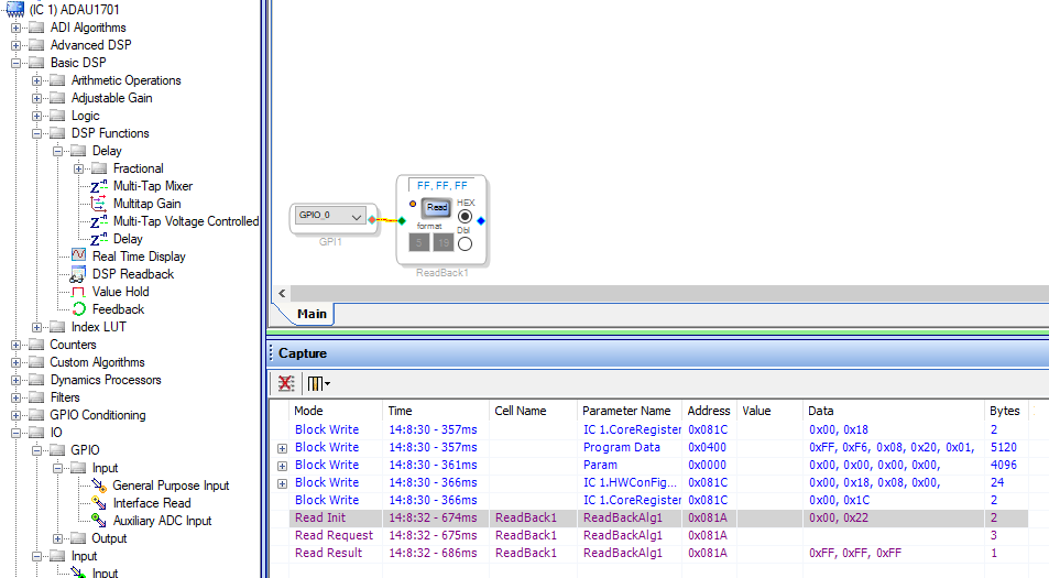
In your SigmaStudio schematic, send the GPIO signal to a DSP Readback cell, and poll the readback register with a microcontroller. (You can see which register to poll by clicking the "Read" button on the cell and looking at which address is being polled in the Capture Window). Then, connect MP0 alternately to 3.3V and GND. Does the microcontroller see the changes in the output?
Alternatively, you can use a square wave source, and monitor the readback in the same way; then you won't have to touch the hardware for your test.
Joshua
Hello Sachr,
Do you have the ability to directly program and control the part from SigmaStudio?
That would answer some questions.
I started a new program and put in an input call and two output sells pointing to the analog output. That is it. When I download it there is no signal on MP9. Then I enable the GPIO registers to set MP9 to be SDATA3 and setup MP10 and 11 to be the LRCLK and BCLK and set it to be a master to give it bitclocks. I still do not see any data. Just zeros as it should.
Then I placed two output cells and set it to digital outputs 6 and 7 and then I see the ADC data. So it only sends data when it is told to. So there is something else going on.
Dave T
Hello Dave,
Unfortunately I am unable to program directly from SigmaStudio since I do not have any compatible programmer.
But I checked the I2C communication and found out that all the data is transfered as it is described in the exported system files. So maybe there is an error in the system file export.
I'll attach the zipped project file (with already exported system files) so maby you could check both for either errors I made or errors made while exporting the system files.
The attached project gives me the following behaviour: On DIG6 and DIG7 you can hear the right stereo signal of the ADC input and on the left DAC output you can hear the left ADC input signal.
PassToAmp2.zip
Hi Sachr,
i already try all ADAU1701 input output combination :
ADC to DAC
ADC to I2S
I2S to DAC
I2S to I2S
All of them is working normally.
Please pay attention :
SDATA_IN0 is not assigned to MP1. It is assigned to MP0.
Also SDATA_IN1 is assigned to MP1.
Please check again your code, your wiring,
your setting, polarity of BCLK, clock, etc..
Good Luck.
Hello,
I re-checked everything and unfortunately i still could not find the error
Hi Sachr,
Have you try selfboot mode ?
Please log in to reply.