ADAU1452 : Data is shifted when reading EEPROM through DSP
Hello,
During my developments to flash the DSP Selfboot data onto the dedicated EEPROM through the DSP, I came across something rather odd...
When I read the last compilation through DSP, the data is shifted by one bit. I use the SPI interface.
But, if I check the data sent by the eeprom to the DSP, it actually is consistent (i.e. it reads 0xAA, 0x00, 0x00, 0x10 as it should) and the selfboot works well.
Another thing that I can't explained is that the shift direction is different between my EVAL-ADAU1452 and my custom board.
My board reads 0x55, 0x00, 0x00, 0x08. Shifted one bit right compared to the expected data.
The eval reads 0x54, 0x00, 0x00, 0x20. Shifted one bit left compared to the expected data.
instead of 0xAA, 0x00, 0x00, 0x10.
Now, this happens with the EVAL-ADUSB2EBZ, but only when the IOVDD is set at 1.8V, it works fine when it is set at 3.3V... My custom board has an IOVDD at 1.8V as well.
Any idea what might be the cause of this behaviour ?
Thanks for your help,
Clement
Audio Signal Processors
adau1452
spi
eeprom
microcontroller
sigmastudio
SigmaDSP Audio Processors
selfboot
Show More
Hello Clement,
This is a good one...
So your board has IOVDD set to 1.8V and I know the EVAL-ADAU1452 board is set to 3.3V. So setting the USBi to 1.8 is not a good idea when using the Eval board and likewise, setting the USBi to 3.3V when using your board is also not a good idea.
So when the USBi is properly set for the IOVDD voltage of the target device it is not correct?
Am I to guess that the program is loading up and running OK in the DSP? That this problem is just in the verification?
I certainly have not seen this. We do use the 1.8V setting a lot with our Class-D amp evaluation boards so I know the USBi works well at that voltage.
So this shifting you are seeing on the screen in SigmaStudio correct?
Dave T
Hello Dave,
When the USBi is set on 3.3V for the EVAL ADAU1452 (matching voltages), it works fine, data read on the capture window of sigma studio is consistent.
When it is set to 1.8V, it is not (but as you said, voltages don't match so this is kind of irrelevant, yet I observe a bit shift as well)
On my custom board, IOVDD is at 1.8V, I set the IOVDD of the USBi at 1.8V as well, and even if voltages match, there is a bit shift on the data read in the capture window of sigma studio, and in the data read by my microcontroller.
But yes, the program loaded when writing is correct as it runs properly when selfbooting, and the data is consistent when I watch it on the side of the Master Spi (Between eeprom and dsp).So it seems that the problem is only happening on the data sent from the DSP to sigma when reading through DSP...
Any clue ?
Clement
Thanks Clement,
Your explanation clears up a few things.
Do not set the USBi to 1.8V and then connect it to the evaluation board. This is not good for the USBi. The voltage coming in is exceeding the power rail voltage which causes the ESD protection circuits to turn on. Not good. Then the signal thresholds for a 1 or 0 are all wrong. So this will cause errors in the transmission of data.
On your board I think this comes down to a signal integrity issue. At 1.8V the drive strengths are much weaker so capacitance on the PCBs and the length of the signal lines all have more effect. So the first thing to try is to adjust the Pin Drive strength on the DSP. There are registers for this and the default is the minimum strength.
So anything that is an output from the DSP you can increase the drive strength. For signals coming into the DSP we have no control over those signals. So you can adjust the outputs to the EEPROM that are on the master port and the outputs to the USBi that are on the slave port.
So that would be the MOSI on the master port.
The SCLK pin on the master port.
The SS on the master port. Those are all outputs.
The MISO on the slave port is an output. Everything else on the slave port comes from the USBi and there is no pin drive adjustments on the USBi. We do use the USBi a lot on Class-D amp boards that are all set to 1.8V and we do not have any issues so it should be fine.
Do you have at least a 4-layer PCB with the internal layers being a ground or power plane?
You might need damping resistors on the SPI lines if you are trying to run at fast speeds.
Here is a screenshot of where you can find the settings.
Dave T
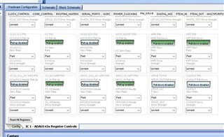
I just remembered one other thing. There are series resistors on the SPI lines on the USBi for protection to prevent damage to the USBi. They are rather high value. If this still does not work then changing the resistors might help out. It would mean your board has a lot of capacitance and probably long lines but we should be able to get it to work.
Do you have the ability to remove and replace 0402 resistors? They are on the smaller size...
Dave T
Hi Dave,
I tried changing the drive strength of the pins and it doesn't change anything.
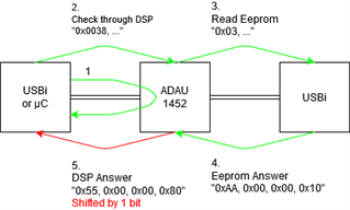
Here is a schematic of what goes right and what goes wrong.
Writing and reading data inside the DSP memory works fine, let's says I change the value @ 0x18D2, if I read the data back (with the "read/write window"), the answer is consistent.
When I Check last compilation through DSP, I see the data sent to the DSP is ok (0x0038)
I also see the request from the DSP to the EEPROM is OK (0x03, ... corresponding to my eeprom datasheet)
The eeprom answers to that request correctly, with the data previously written inside it (8-bits sentinel 0xAA, 24-bits address 0x000010) and so on...
This is where thing go south... The data sent from the DSP to the USBi (or my µC) is shifted. Sigma studio reads 0x55...
So, write to DSP works fine, Read from DSP works fine, write to EEPROM works fine (through DSP), read from eeprom through dsp work fine until the data is transmitted from the DSP to the USBi.
So it seems that there is some kind of "corruption" in the data transfer between the DSP-SPI master receive buffer and the DSP-SPI slave transmit buffer... I may be wrong here but that is what I observe.
Hope this helps,
Clément
Hello Clement,
I am assuming your diagram label is slightly wrong, the block on the far right should be labeled EEPROM, Correct?
Also, the data is not exactly shifted entirely. The lowest byte would be 0x08. Was the 0x80 a typo?
If it is a typo then it would be shifted as you are saying.
So now I need to know your PCB details.
How many layers?
What are the layers used for?
Can you make a PDF of the layout? Let me know which part is the EEPROM if it is not clear.
I would like to see the PCB traces from the EEPROM to the DSP and from the DSP to the USBi connector.
Also, I never asked but I assume you are using SPI correct?
Dave T
Hi Dave,
Yes, you are right, I made mistakes on my diagram, I meant to put EEPROM on the right and the last byte is 0x08. Friday evening I guess, sorry about that.
We have a 6-layers PCB. Signals are on layers 3 and 4. Layer 2 is ground, layer 5 is 1.8v basically.
I can't share the layout with you.
And yes, I use the SPI interface.
But I believe ths SPI bus is working fine because if I read the internal memory of the DSP, it returns fine.
We have ESD protections such as a 3V ESD diode, a BLM and a capacitor to the ground on the connector, might this have a side effect ?
Thanks,
Clement
Hello Clement,
So is the DSP properly running the program after it selfboots?
If it is properly running then the data path between the EEPROM and the DSP would be working properly.
So it leaves it to the segment between the DSP and the USBi. You said you are reading memory properly just not the EEPROM data being passed through the DSP. This is an interesting problem and it may be related to running at 1.8V and then the PCB layout and design details. I will think about this a little more but I am not sure where to go from here. I don't think the pass-thru program is pushing the limits of speed.
The ESD protection certainly might be causing or contributing to the issue.
I am suspecting a PCB issue at this point.
Dave T
Please log in to reply.