ADAU1761 full scale output on serial port
Hello,
I need some help understanding the serial port output numeric format from an ADAU1761 CODEC on a custom PCB.
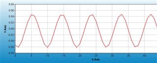
I've set up the CODEC for ADC single ended line in routed directly to serial port output (i.e. no DSP) and am reading the audio data into buffers in a BF706. AVDD = 3.3v. Fs is set up for 48kHz with 24 bit samples. When I put a 2.8v p-p waveform of any frequency into negative side line in L (positive side connected to CM), I obtain a ~0.12 p-p waveform in BF706 when plotted in CCES. Given the 1.23 numeric format of the ADAU1761, I'd expect to see a near full scale waveform of 2 p-p (i.e. -1 to 1 signed fraction). I can hear the waveform just fine at a reasonable level via the ADAU1761 headphones when routing MIXER1 to MIXER3 and headphone L. Volumes LINNG and LADVOL are set for 0dB. Any ideas on what I am doing wrong? Thanks!
Serial port is set up for I2S with one BCLK delay.
Edit Notes
Added serial port configuration description.
[edited by: David_Ashman at 5:24 PM (GMT 0) on 14 May 2020]
Audio Signal Processors
SigmaDSP Audio Processors
adau1761
Hello David,
Since it seems that you have a good signal when routing mixer 1 to mixer 3 I can assume you have the LINNG set properly and is selected as a source into mixer 1.
This tells me that the signal into the left ADC input is there.
I suggest that you look at the actual serial data coming out of the serial port with an oscilloscope. It is easy to see if the audio is really low or close to full scale. Then you will confirm that the serial port is setup properly.
The format of the digital data is 2's compliment.
Dave T
Thank you for the quick reply DaveThib I've captured some scope plots and are included below. Bottom line is that with a full scale 2.8v p-p signal at the input to CODEC, I would expect to see all bits toggling on the L channel of serial port; which I'm not seeing. It appears that 2 MSbits are missing. Do you agree? Other than LINNG and LADVOL, are there any other registers that control ADC level from L line in sent to serial port?
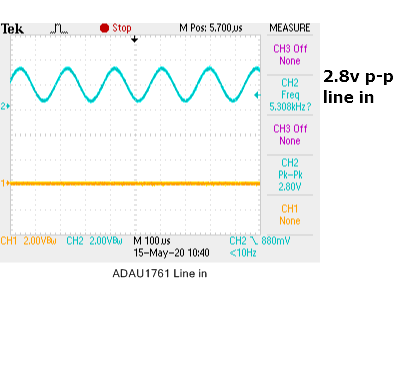
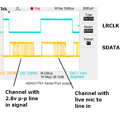
Hi DaveThib I wanted to share some additional findings and ask if you can verify with design engineering.
1. When ADC is routed directly to serial port output, LADVOL (Reg 0x401A) and RADVOL (Reg 0x401B) have no effect on data sent to serial port when DSP is bypassed.
2. When Line In Neg is used in a single ended manner (i.e. bypass the differential amp) and a full scale 2.8v p-p signal is input, the maximum 1.23 numeric format swing on serial port is not -1 to 1. The maximum swing is shown in the above scope image with infinite persistence; which appears to be 2 MSbits less than full 1.23. Setting LINNG (Reg 0x400A) and RINNG (Reg 0x400C) to +6dB do not allow the data seen on serial port to increase beyond this pattern. For full scale analog input, I would expect all bits to toggle. Setting LINNG and RINNG to values less than 0dB attenuate the full scale analog signal as expected.
Thanks!
Hello David,
Sorry for the delay. I have been taking care of some other pressing matters and I also wanted to actually set this up in the lab to get screenshots.
It looks like the level into the part is low. The only gain control before the ADC in your signal flow is the LINNG (register 0x4003). If you have this set to +6dB and the data is still not up to full scale then the level into the ADC is too low. One other option is if you are not AC coupling into the ADC and you are loading down the common mode voltage. That would lower the level into the ADC and it would also not make it go negative if it is pulled down. The common mode voltage sets where the "0" level is and then the signal will go positive or negative as it relates to that voltage.
That said, your scope capture does look like the signal is riding up on a DC level.
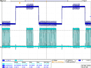
So I set the Audio Precision for 2.8 Vpp and then captured the serial output.
The Audio Precision serial input measures this as -0.1dBFS so I will call that full scale.
The other channel had no signal on it so it is just noise/DC offset. ( I did not turn on the HPF)
This is coming into the LINN with a single ended signal. The gain control is set to 0dB and of course the ADC level controls are at 0dB.
Dave T
Hi DaveThib Thanks for running that test. I am getting full scale on the serial output line now with full scale input LINN wave. Turns out, since this is a USB audio device, the Windows driver was coming in and decreasing the volume as soon as the BF706 booted up. BTW, my line in driving circuitry is AC coupled and the signals at LINN and RINN are properly centered on 1.65v. Thanks for the help - problem solved.
Great! Glad you were able to figure it out. It can be tricky to track down an issue when there are many places where something can be off.
Good work!
Dave T
Please log in to reply.