Filter co-efficient
Dear Team,
We have tried calculating filter coefficients theoretically with following parameters
Parameters:
Filter Type : General Eq (2nd order ) High Pass Filter
Sampling frequency(fs) : 48000Hz
Cutoff frequency(fc) : 4Hz
Q factor : 0.7
Gain : 0
We have referred formulas from General 2nd Order High pass filter section from analog devices website. The filter coefficients calculated is different from coefficients observed in capture window of sigma studio.
Kindly find the observations as below
Coefficients observed in capture window
Coefficients calculated in excel sheet
EQGenFilterDPS300Alg1B2_1
0.99962610006332
0.99962607220141
EQGenFilterDPS300Alg1B1_1
-1.99925214052200
-1.99925214440281
EQGenFilterDPS300Alg1B0_1
0.99962610006332
0.99962607220141
EQGenFilterDPS300Alg1A2_1
-0.99925225973129
-0.99925228142940
EQGenFilterDPS300Alg1A1_1
1.99925202131271
1.99925200737623
Also when we try to load the calculated coefficients directly in "IIR Coefficient" mode available in General Eq (2nd order ) different values are observed in capture window
Coefficients observed in capture window
IIR Coefficients Loaded
EQGenFilterDPS300Alg1B2_1
0.99962610006332
0.99962607220100
EQGenFilterDPS300Alg1B1_1
-1.99925214052200
-1.99925214440300
EQGenFilterDPS300Alg1B0_1
0.99962610006332
0.99962607220100
EQGenFilterDPS300Alg1A2_1
-0.99925225973129
0.99925228142900
EQGenFilterDPS300Alg1A1_1
1.99925202131271
-1.99925200737600
Your explanation of these observations is awaited.
Regards
Hermione
David <David.Thibodeau@analog.com>
sigma
KJ BOB
sigmastudio
Hello,
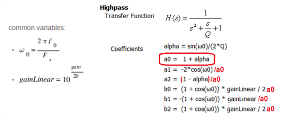
Calculating these coefficients gets quite muddied by different conventions in the literature -- I've seen flipped meanings for the a and b coefficients, and minus signs in different places. Some of this confusion can still be found in the SigmaStudio Wiki, although it's been improving. For example, here's what it presents for the 2nd Order Highpass coefficients:
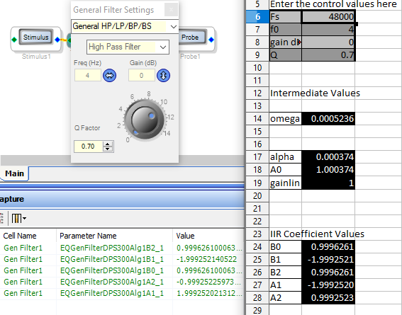
Included is coefficient a0, which the Sigma DSP's don't explicitly use -- to save instructions, Sigma DSPs fold a0 into the other coefficients. This means that we need to divide all the other coefficients by a0, as shown in red above. Once this is done, the calculated coefficients come closer to those shown in the Capture Window for the stock highpass filter, as shown below:
The major difference between the Capture Window and coefficients typed into the IIR Filter boxes is the sign inversions for the a1 and a2 coefficients -- I can't answer why these flipped signs don't appear in the coefficient formulas themselves, it's just an example of ambient coefficient confusion. I also can't explain the small differences in magnitude except that it's typically beyond the seventh decimal place. Seven digits (nearly 24 bits) of resolution is good enough for any filter I've worked with.
Best regards,
Bob
Good to see you here again, Bob.
The small differences in magnitude come from conversion from floating point to fixed point. What you see in the Capture Window is a representation of the exact hex value written to the DSP.
Here is the Excel formula which will take a float value and return the Capture Window value.
For processors using 8.24: CEILING.MATH(put_cell_here * BITLSHIFT(1, 24)) / BITLSHIFT(1, 24)
For processors using 5.23: CEILING.MATH(put_cell_here * BITLSHIFT(1, 23)) / BITLSHIFT(1, 23)
I'm not sure yet why the formula to go from float -> fixed uses CEILING instead of FLOOR. It's just a 1 LSB difference, but I'd like to know. In my microcontroller code, I use int32_t(value * (0x01 << 24)); which I believe will floor.
I know the Wiki makes the coefficient formulas confusing. I'll add this to my list of things to update in the Wiki. It will take some time for me to go through and verify all the formulas.
Joshua
Thank You That helps
Please log in to reply.