ADAU1761 initialisation issue
Hello SigmaDSP support team,
My customer evaluates ADAU1761 on the prototype. DSP doesn't start correctly after power on and the customer has to perform software reset after power on and write all required registers once again.
Could you please give recommendations on how to start ADAU1761 without software reset or give an initialization code example?
The customer initialization code as follows:
void ADAU1761_Init(void)
{
uint8_t p;
uint32_t m;
osStatus statusMutex;
statusMutex = osMutexWait(mvMutexAICHandle, portMAX_DELAY);
ADAU1761_WriteReg(ADAU1761_R0, 0x00);
ADAU1761_Init_PLL(0x00, 0x7D, 0x00, 0x0C, 0x20, 0x00);
ADAU1761_Init_PLL(0x00, 0x7D, 0x00, 0x0C, 0x20, 0x01);
while(!ADAU1761_Lock_PLL()){};
ADAU1761_WriteReg(ADAU1761_R0, 0x0F);
for(m = 0; m <
(sizeof(preferredSettings)/sizeof(registerSetting_t)); ++m)
{ADAU1761_WriteReg(preferredSettings[m].addr,
preferredSettings[m].data);}
osDelay(ADAU1761_DELAY);
DMA1_Stream4 ->CR &= (~DMA_SxCR_CIRC);
statusMutex = osMutexRelease(mvMutexAICHandle);
if(osOK != statusMutex) mvRokotError_Handler("AIC Mutex");
ADAU1761_Off();
}
Best regards,
Dmitry
Audio Signal Processors
SigmaDSP Audio Processors
adau1761
Hello Dmitry,
This is what you are sending to the PLL
Unknown said:
ADAU1761_Init_PLL(0x00, 0x7D, 0x00, 0x0C, 0x20, 0x00);
I am not sure which is byte 0 and which is byte 5.
I am assuming that the registers are written from right to left on this list. I am making that assumption because of the 00 then 01 of the two writes you are doing. That would disable then enable the PLL.
So looking at the datasheet this is what I think are the PLL configuration you are using:
Byte 0 = 0x00
Byte 1 = 0x7D
Byte 2 = 0x00
Byte 3 = 0x0C
Byte 4 = 0x20
Byte 5 = 0x00 Then 0x01 after the second write.
So byte 4 is the byte of interest.
0x20 means that the following:
R = 4
X = 1
PLL Type = Integer.
Since it is set to an integer type, the other M and N values are ignored so they do not matter.
So what frequency is the master clock? ( If it is 12.288MHz then you are fine. If it is not then there is an issue)
Are you using SPI or I2C?
What frequency of SPI or I2C clocks?
Thanks
Dave T
Hi Dave,
Thank you for your answer.
The customer is using I2C with a clock rate of 400kHz. Masterclock is 12.288MHz.
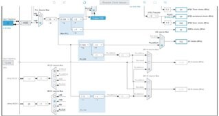
ADAU1761 clocking settings are listed below:
Hello rotax,
The clocking diagram is not from the ADAU1761. I do not recognize it.
400kHz is the max rate so you could try to lower it to 100kHz as a test. I don't think this is the issue but it is worth a try.
Is it possible to capture the I2C communications to see the data that is being sent and the timing?
Dave T
Hi Dave,
Sorry, the clock diagram is from STM32.
The customer has reduced I2C rate down to 100kHz, nothing has changed.
So, they still have to perform software reset and write all required registers once again after startup
Best regards, Dmitry.
Hello Dmitry,
How long after power up are you trying to program the 1761?
You said you have to perform a software reset after power up but this part does not have a soft reset or even a reset pin. So what is being reset?
Can you capture the I2C communications from power up?
Thanks,
Dave T
Hello Dave,
The customer asks: Do any recommendations about the minimal time between power-on and programming ADAU1761 exist?
Best regards, Dmitry
Hello Dmitry,
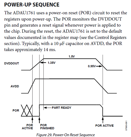
There is some mention of this in the datasheet. Here is what is written.
It mentions that once the AVDD reaches the threshold when POR is active to when POR is done is 14ms. The graph does show that the rise time of AVDD and the completion of the rise time of DVDD is shown but no time is given. This is because it depends on the power supplies and filter caps on the customer PCB so we cannot specify this time exactly since it is out of our hands. So you could capture these voltages on a scope to get a much more exact value for your design.
Dave T
Hi Dave,
The customer has resolved the issue.
Thank you so much for your support.
Best regards, Dmitry
Please log in to reply.