Stereocoder 38Khz multiplex not working on adau1451
Hi,
I build de stereocoder in adau1451 from the schema in adau1701. It works accept the 38Khz won't come out.
Did try to change the clock settings and sample rate but solves nothing.
Stereocoder-1701.dspprojstereocoder-1451.dspproj
Audio Signal Processors
adau1451
SigmaDSP Audio Processors
adau1701
Hello,
The ADAU1701 has buitt-in converters and can easily switch sample rates with no HW mods except perhaps the DAC output filters. On the other hand, the -1451 needs an external codec to provide analog in and out -- and the codec sample rate is set separately. What hardware are you running your project on? If it's a stock eval board or anything that uses a AD codec in standalone mode, the DAC remains at 48K even when your 1451 project is at 192 K. You'll need to run both the -1451 and the codec at 96K (or 192K if outputting both MPX sidebands).
Best regards,
Bob
Hi Bob,
I am using a raspberry pi 3b with a hifiberry dac-dsp on top. Using the spdif input and the analog out by the dac pcm1502a.
Am I understanding correctly that the spdif is interfering with input and output? because I don't use any codec yet.
Can I test a setup without audio input, so that I can at least isolate the problem?
Thanks in advance for your answer.
Hi Ben,
Thank you for attaching your project as it makes clear what you're working on. You can test without audio input by substituting oscillators. The arrangement shown has both in-phase and out-of-phase signals so it should provide both baseband and MPX outputs. Note that the VCO input voltage needs to be reduced 4x to get your 19K & 38K outputs at the 192K sample rate -- hopefully that's the only thing that's wrong! If not it will take some more digging.
The data sheet for the PCM5102A DAC shows that it can adapt via internal PLL to your 192K rate as long as hifiberry set it up that way (I think). Do they show how to set up the -1451 clocks for 192K operation -- either in the docs that come with the board or on their support site? I'm afraid I cannot help with the clocks because my 1452 eval board has its AD1938 DAC stuck in 48K standalone mode. As soon as make any change to the Clock Gen1 settings the audio mutes, and I've learned (the hard way) not to suggest anything that hasn't been tested.
Best regards,
Bob

Hi Bob,
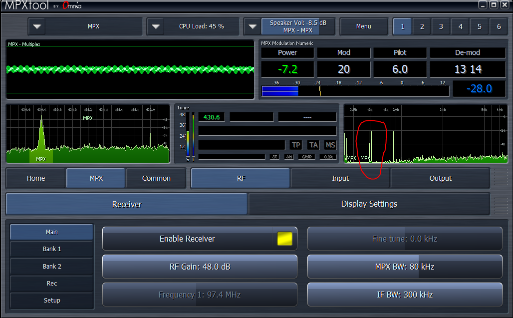
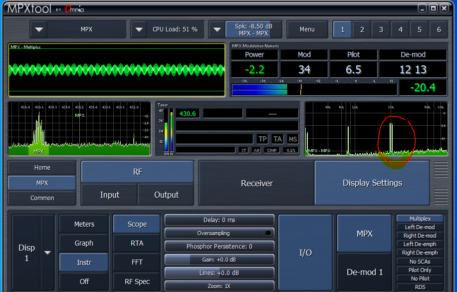
I made your input working on the 1701 and the 1451. On the audio part its working but as you can see on the images the MPX shows up @ 10KC (mpx(wrong) 1451 and look @ the correct output from the 1701.
1451 audio and output pilot 19KC and mpx 10KC Did also made a 38KC directly from a sine wave but outputs the same
1701 audio and output pilot 19KC and mpx 38KC
I
Hi,
I like your analyzer readings! In your project the MCLK setting calls for a 24.6 MHz crystal. Most boards I've seen use a 12.288 MHz crystal, so if hifiberry employed a 12.288 MHz crystal on the board, change this setting. The base Fs refers to whether it's 48K or 44.1K and does not concern the higher rates.
You can also perform this test: Make a copy of your project (so the copy project has the same HW settings). Replace the MPX circuitry in the copy project with just one 20 kHz oscillator feeding the DAC output directly, then read this output with your analyzer. If the output frequency is other than 20 kHz then your HW sample rate isn't 192K -- and thus your clock generator(s) are not set correctly. The -1451's HW sample rate settings involve the PLL for the core clock which remains at about 295 MHz, so we don't need to change this. But then a set of clock gens do the sample rate and other functions. These confuse me, yet there's various threads on EZ which may help you get all this set correctly. One of them is here. Once you get your copy project to output 20 kHz, duplicate the new HW settings on your MPX project.
If it still isn't working, hopefully a ADI SE will chime in during the work week.
Best regards,
Bob

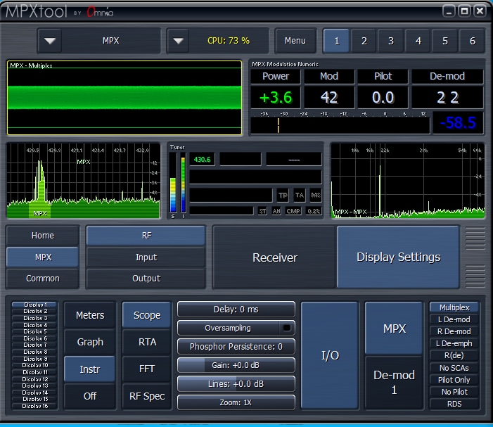
Hi Bob, the signal is there, but it also shows up as sideband in 38KC audio. strange... cant set the freq higer then its drops down as a / div from fs. Regards, Ben
Hello Ben,
Sorry I have been distracted and also travelling.
I just looked at your project from your first post. I quickly scanned the conversation so there may be some details I missed.
First, it looks like you are coming in using SPDIF. Is the SPDIF running at 192kHz? The 1452 SPDIF will not do 192kHz so you would have to move to a Sigma350 like the 1463.
Then you are going into the core where SigmaStudio is set to 192kHz. This will tell SigmaStudio that the DSP is running at 192kHz so it will produce the correct code for that frequency. However, SigmaStudio has no idea what the DSP is actually doing.
Your settings under the clock control is for 48kHz. So from what I see you are running the core at 48kHz.
Even this is an assumption. The registers may be set for 48kHz but it is still dependent on the actual clocks that are coming into the DSP. So what are those? Is the MCLK 12.288MHz?
Then it looks like you want to go out of the serial port_0 with the 192kHz audio? That serial port registers are also set for 48kHz. So that is another problem.
So where are you with this problem now?
Dave T
Hi Dave,
As you can see i try two build a stereocoder. That needs to run @192KC. This works on the 1701 and now want to make it work on the 1451 as part of the hifiberry DAC+DSP solution on a R-PI 3B
I tested with no spdif using tone generators as shown by KJBOB.
Settings are MCLK 12.288MHz, startpulse fs*4 @192KC, serial output set two clock generator 3, fs *4 sampling rate and now setting up clkgen 3 n and m ratios.
2.288 MHz ÷ 4 × 96 = 294.912 MHz
294.912 MHz ÷ 1024 × 2 ÷ 3 = 192 kHz
So far no succes
Hi Dave,
Can't the adau1451 generate signals above 24KC in this configuration?
Then I can put the project aside and request a refund from hifiberry.
Regards, Ben
Hi Bob, can you help me further with this problem? Unfortunately I have not had a response from Dave.
Regards, ben
Hello Ben,
What is the frequency of your master clock coming into the 1451? In reading back through the thread it is not clear what it is.
You have been using SPDIF input correct?
Are you using SPDIF output?
Which serial output port are you using to get signals to the DAC?
Please send your project again. There have been many changes and things discussed since the last time. I also want to see how the clock generators are setup.
If the DSP core is running at 192kHz then the core can produce audio signals up to fs/2 = 96kHz. The serial ports are able to transmit these signals.
Now here is a possible source of problems. If you are using an evaluation board and using jumper wires to jumper the serial port clocks and data over to this other board that has the DAC, then you are going to have a lot of problems getting the signal to be good with no clicks or pops and possibly any signals at all. This is because of signal integrity ( signal reflections and other factors that distort the waveform ) Then there will also be timing issues due to the length of the wires. Running at 192kHz over fly-wire is very difficult. We deal with this often in our labs when connecting to an Audio Precision digital interface. We have to use special low capacitance cables and they are short, perhaps 20", and we still have difficulty. You may have to increase the drive strength of the clock and data outputs but sometimes that does not work due to the reflections. I have had to solder on series damping resistors to make it work. So this may also be part of the problems you are experiencing.
One other final thing, are you using an oscilloscope to look at and measure the clock frequencies coming out of the 1451?
If you are using SPDIF output then you will have to change to a different part but it is not a significant change.
Dave T
I've simplified my approach to avoid having too many things that could affect the design and thus the problem.
1. I don't use SPDIF inputs or outputs.
2. I'm using the serial output sdata_out0
3. core is running @ 192kHz (base fs *4)
4. Using a hifiberry board DSP -DAC with no jumper wires to jumper
5. I use a spectrum analyzer special for FM modulation you can also read the frequency.
I also recognize the known problems with cabling, but as said they are not used.
A design like this will not work, and i dont understand
thanks in advance for your help
Regards, Ben
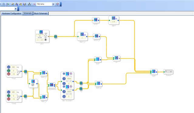
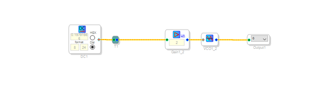
stereocoder-1451-v1.dspproj3531.stereocoder-1451.dspproj
i added the original design, just for info
I've made some changes to the clock settings.
Give it a try...5850.stereocoder-1451-v1.dspproj
yes, this works. thanks a lot
now i will check if i can use the inputs from spdif
Please log in to reply.