AN ADDRESS ERROR OTHER THAN 0X68
Hello, there.
I can't run ADAU1701 at a different address than 0x68. The hardware is the same. I'm just changing the link to the address pin. It doesn't work. The Sigma studio device is not connected error. Is there any other setting that we need to change from the app or hardware when we change addresses? I'd appreciate your support. we're trying to get 2 different adau1701 on one line.
Audio Signal Processors
addresses
i2c
microcontroller
2 aDAU1701
sigmastudio
SigmaDSP Audio Processors
adau1701
Show More
Hello,
Set the 1701’s address by logic levels at ADDR0 (pin 7) and ADDR1 (pin 20). The default with both pins grounded is 0x68. If for example you rewire pin 7 of one chip to 3:3 v, its address becomes 0x6A. Table 16 on p. 23 of theADAU1701 Data sheet gives the address for each HW pin setting.
Best regards,
Bob
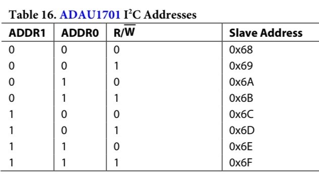
Hi. I tried all the apps you mentioned. I also reset the selfboot pin to zero. I also checked it with a measuring instrument. It doesn't, unfortunately. How many different addresses can I define for Adau1701. it shows 8 in the application, but there are not 4 in the datasheet. What can I do about it?
Hi,
The -1701 has two HW address pins which define four addresses— so you can have up to four 1701s on one bus. Where I work we produce a product whose microcontroller has two I2C buses, and three -1701s on each, for a total of six. Each 1701 has its address pins hardwired according to its corresponding address in the HW setup tab of SigmaStudio. They all work fine together.
Since 1701 has a choice of only four addresses, perhaps the others shown on the app are for other chips.
Best regards,
Bob
Hello. I am also doing a similar study. 1701s only work at 0x68. Unfortunately, it doesn't work when I change the address using the ADDR0-1 pins. My settings for the selfboot pin are also ok. What else should I change? can you give an idea?
Hello.
I need a little more info. Could you show your hardware schematic? How are you booting your 1701s — from a microcontroller, a E2PROM (selfboot), or from a USBi (Link Compile Download from SigmaStudio)? It appears from p.27 of the data sheet that selfboot only works at address 0x68. Our system boots from the micro, we also have jumpers we can lift then plug in a USBi and boot one bus at a time (three 1701s) from SigmaStudio. Unfortunately, I’m not the digital wiz on this project so I’m running out of ideas. Perhaps when the ADI support engineers return after the weekend, they could make additional suggestions.
Best regards,
Bob
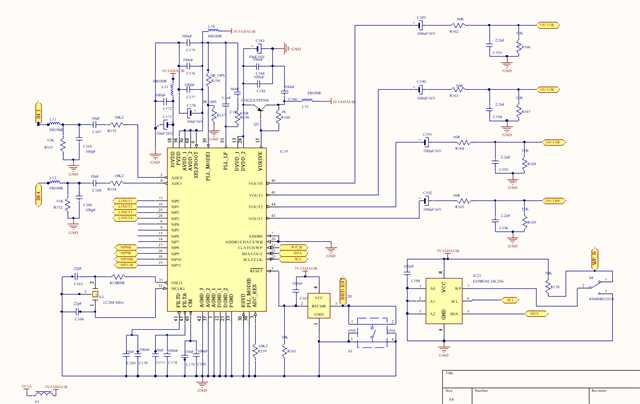
Hello. Thank you for your interest. I shared my schematics. I disconnected the selfboot part from 3.3 volts and pulled it to GND. Don't be fooled by the scheme. I have a single line and I'm trying to run it via USBi. Unfortunately, it didn't work even when I plugged in a single ADAU.

Hi,
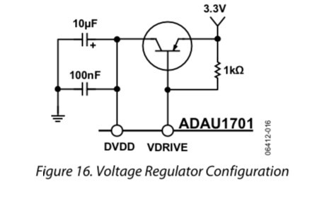
You do have the chips’ ADDR0 pins wired differently so I’m surprised it isn’t working. One error I do see: The PNP voltage regulator transistor’s emitter and collector are flopped (compare to the data sheet p.19).
Best regards,
Bob
Hello YLmazGNDZ,
I agree with Bob that you need to change the regulator pass transistor connections. This may actually be part of the issue if the DVDD is not correct.
I also did not see any other issues with the schematic during my quick glance.
The problem you may be having has to do with Selfboot and that you have two EEPROMs on the same I2C bus. So both DSPs will be trying to be a master at the same time on the same bus and they cannot handle that. You will have to separate the two I2C busses when you try to selfboot. You need to have some jumpers.
1) Jumpers to take the DSP out of Selfboot mode when working using SigmaStudio.
2) Jumpers to isolate the two I2C busses when you are not using SigmaStudio and want to selfboot.
3) You probably can get away with loading the exact same program into both EEPROMs. Years ago we did try this in the lab, we setup about five eval boards and programmed all the EEPROMS at one time. The EEPROMS would all provide the ACK at pretty much the same time so it worked. However, if you need to have different programs then you need to somehow setup the SDA and SCL out of the USBi to be connected to only one EEPROM at a time so you can program them.
I have seen people use transistors to automatically pull down the Selfboot pin when the USBi is connected by using the 5V DC output of the USBi to control a transistor. Just be careful to not put the 5V onto the pin. You can do the same with I2C bus repeaters to do the connections and disconnecting of the two I2C busses. That gets a little more complicated but can be done.
Dave T
Please log in to reply.