I calculate IIR Coefficient through mcu and the filter generated by General HP/LP/BP/BS is inconsistent
I calculate IIR Coefficient through mcu and the filter generated by General HP/LP/BP/BS is inconsistent
My IIR Coefficient formula, refer to the forum https://ez.analog.com/dsp/sigmadsp/f/q-a/65799/eq-low--and-high-shelf-filter-coefficients-comming-back---mysterious-s-factor
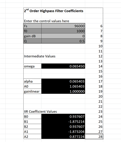
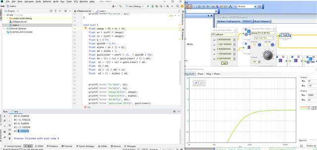
excel Calculation results:
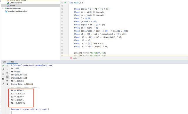
my muc Calculation results:
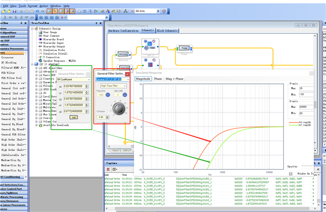
now sigmaStudio 4.7
I found that the data A1 and A2 generated by this sigmaStudio 4.7 are inconsistent with the negative values I generated.
Safeload Write
Time: 01:34:34 - 841ms
IC: IC 1
Cell Name: X_OVER_01.HP1_5
Param Name: EQGenFilterDPS300Alg161A2_1
Param Address: 0x0000
Param Value: -0.877223670482636
Bytes: 4
Param Data:
0xFF, 0x1F, 0x6E, 0x45
Safeload Write
Time: 01:34:34 - 842ms
IC: IC 1
Cell Name: X_OVER_01.HP1_5
Param Name: EQGenFilterDPS300Alg161A1_1
Param Address: 0x0000
Param Value: 1.87320441007614
Bytes: 4
Param Data:
0x01, 0xDF, 0x8A, 0x53
This problem has been bothering me for several days, looking for help from the official website
#include <stdio.h>
#include <math.h>
#define PI 3.14159265358979323846f
#define fc 1000
#define fs 96000
int main() {
float omega = PI * fc / fs;
float sn = sinf(omega);
float cs = cosf(omega);
float Q = 0.5f;
float gainDB = 0.0f;
float alpha = sn / (2 * Q);
float a0 = alpha + 1;
float linearGain = powf(10, gainDB / 20);
float b0 = ((1 + cs) * linearGain) / (2 * a0);
float b1 = -((1 + cs) * linearGain) / a0;
float b2 = b0;
float a1 = -(2 / a0) * cs;
float a2 = (1 - alpha) / a0;
printf("fc:%d\n",fc);
printf("fs:%d\n",fs);
printf("omega:%lf\n",omega);
printf("alpha:%lf\n",alpha);
printf("A0:%lf\n",a0);
printf("linearGain:%lf\n",linearGain);
printf("------------------------\n");
printf("B0:%lf\n",b0);
printf("B1:%lf\n",b1);
printf("B2:%lf\n",b2);
printf("A1:%lf\n",a1);
printf("A2:%lf\n",a2);
return 0;
}
float omega = 2 * PI * fc / fs now modify float omega =PI * fc / fs
c code bug:
float a1 = -(2 / a0) * cs;
float a2 = (1 - alpha) / a0;
The negative values of the two variables a1 and a2 are wrong
[edited by: weixiao at 10:32 AM (GMT -4) on 7 Aug 2022]
我已经解决了当前的问题并对其进行了修改
float omega = 2 * PI * fc / fs 现在修改 float omega =PI * fc / fs
我参考维基
https://wiki.analog.com/resources/tools-software/sigmastudio/toolbox/filters/general2ndorder
并测试成功
符合预期的频响曲线
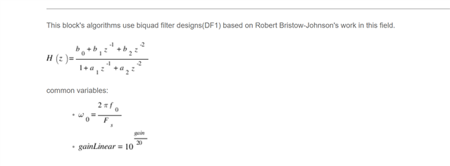
Finally, another question is raised, is there an error in the document, or is the code calculation wrong?
Hello,
I think the wiki is correct. I think w0=2*pi*fc/fs is correct
I dont know why you observe the red curve, perhaps you need to refresh the stimulus/probe ?
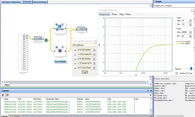
For me the b0,b1,b2,a1,a2 calculated from the wiki are same as calculated in SigmaStudio, and the plots are correct, see the screenshot:
Hello Weixiao,
Though you somehow managed to get both curves matched in the second picture but that doesn't seem right. The curve doesn't seem quite right for the parameter that you have given. So the thing is , the formula should be what's in the wiki. The w0 formula that you used excluding that 2 will not give you a correct result anyway.
We duplicated the same as yours and ended up getting the correct results with the wiki's formula.
And you have filters cascaded in your project. We don't know what are all the parameters being set for those filters. Without looking at your project , It's quite hard to analyze and give you an answer of what's going on there. Kindly send us your project.
Regards,
Harish
Sorry, I can't log in to this account when I post, it prompts me to prohibit authorization
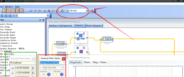
I found that after using the Simulation Probe control, I did not have the motor fs to modify the sampling rate of all controls synchronously. The default sampling rate used by the actual Simulation Probe control is 48khz
Hello,
Can you please describe you problem a bit clearly with your project file?
Regards,
Harish
Hello,
Can you please describe you problem a bit clearly with your project file?
Regards,
Harish
I replied that this account was newly applied by me. My previous account "weixiao" prompts me to refuse to log in when I log in to the forum. I don't know what happened.
I have solved this problem, it's not that the calculation formula is wrong, but the default sampling rate of Simulation Probe control is 48khz, and I set it to 96k

Hello ,
I'm glad that you solved your issue. By the way, could you please tell us how did you set the stimulus and probe sample rate?
I guess it works and runs based on the rate you give at the top (software fs). You can't run stimulus and probe at one rate and your project at one rate. I don't think you can set different sample rate to that (stimulus and probe).
Regards,
Harish
Please log in to reply.