On/off keying in Sigma studio (ADAU1787)
Hi all!
I am currently trying to get On/off keying working in sigma studio but It really is not going my way. I tried the below scheme. Later I will replace the pulse generator with an input from a MCU. Does anyone have any idea of what I am doing wrong or how I would solve on/off keying for both modulation and demodulation?

Hello elibergl,
The frequency input to that pulse module should be between 0 and 0.5 and the duty cycle input should be between 0 and 1.
0 means 0%, 0.1 means 10%, 0.5 means 50%, 1 means 100%. The input frequency can go up to fs/2.
It accepts 8.24 format but ADAU1787 is 5.23.
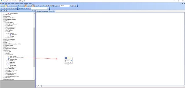
Simply you can use the below block to achieve the same. It also goes between 0 and 1. You can choose the frequency and duty cycle directly.
Regards,
Harish
Hi Harish, Thanks for the answer!
I tried the same setup but is still dose not look like a on/off keying scheme. Any idea of why that is?
Hello ,
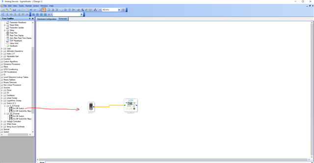
You just want to switch ON and OFF? That is basically a 1 and 0 respectively? The switch block will go between ON and OFF. You can check that by clicking the read button in the readback cell as given below.
Regards,
Harish
Hello elibergl,
Can you define what you mean by "on-off keying"?
When you said this I thought you meant an external button that you want to press once for on and one again for off. A toggle function.
But I see your program is connected to a VCO. So do you want to use it for FSK modulation where a low and a high are two different frequencies? I seem to recall some examples of this on the forum already. Search for "FSK".
So if you can define your terms and also define what you need to do with it this will help us to help you.
By the way, in your example, you are sending a "1" or a "0" to the VCO. This will give you a MAX frequency of fs/2 for the "1" input and DC for the "0" input. So you will be going pretty much from no output to no output. Try something like 0.2 and 0.5. I am just guessing but this will be a percentage of min to max frequency. 20% to 50%.
Thanks,
Dave T
Please log in to reply.