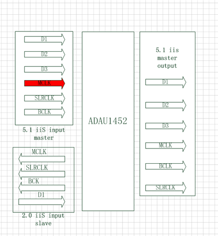
could you tell me how to configure the ASRC for ADAU1452 .This is our system framework
Hi everyone. This is our system framework.
Two IIS inputs, one is the master, one is the slave, and the other is the master output.
could you tell me how to configure the ASRC for ADAU1452 .
thanks very much .
Audio Signal Processors
adau1452
Datasheet/Specs
SigmaDSP Audio Processors
Hello jenkey2008,
In your block diagram, D1, D2, D3 are each stereo line ? Each serial port with BCLK and LRCLK can only drive a single data pin which carries two channels in stereo mode(L/R). You can drive more channels in TDM mode. So if you want to drive three stereo pairs then you have to use three different serial ports for both inputs and outputs.
I have attached a project where I have two stereo pairs of input from two different ports. I run one port as a master and one port as a slave for BCLK , LRCLK as you asked.
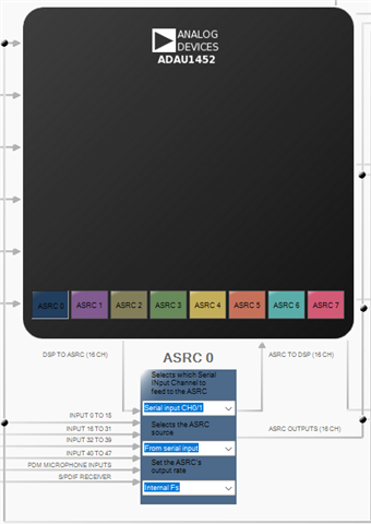
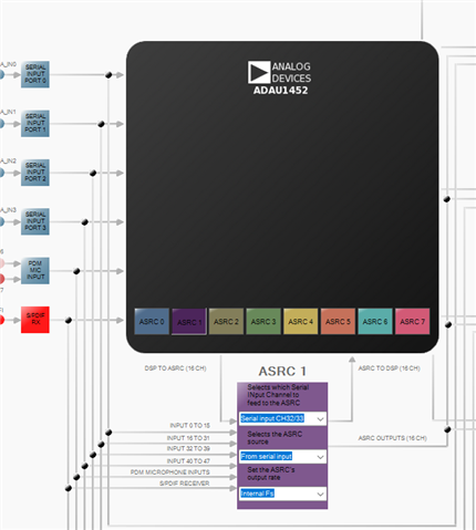
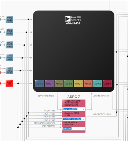
I'm using ASRC 0 and ASRC 1 for getting the inputs from the serial ports. ASRC 0 is getting its input from channel 0-1 of serial input port 0. ASRC 1 is getting its input from channel 32-33 of serial input port 2.
You will not need ASRC for the port that you set as master since the DSP sample clock and serial port clock (master) are from the same clock domain. But the below example uses it for config demo.
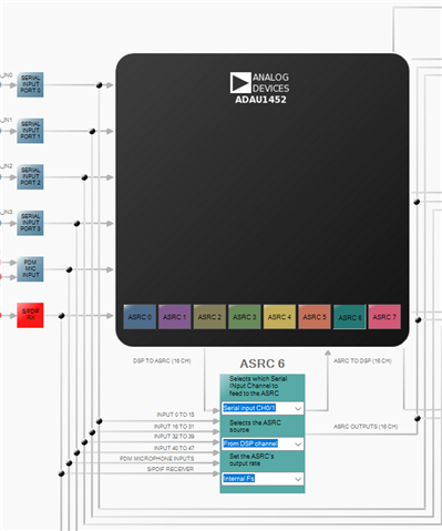
I'm using core rate for synchronization that is internal fs. Then I added few processing elements like volume control then I'm sending that out to ASRC 6 (ASRC output 12-13) and ASRC 7 (ASRC output 14-15).
Don't consider the serial inputs tab in ASRC 6 and ASRC 7. Here also I'm just using internal fs for an example. Without using ASRC out block in your schematic, you can directly send that to serial out in your schematic, Because the signal is already in core rate only. You can choose which rate you want.
Then I'm sending that signal to serial output port 0 (ch 0-1) and serial output port 1 (ch 16-17) via the routing matrix.
Coming to the serial port settings, As I said before, I consider one serial input port as a master and one serial input port as slave. I took Serial input port 0 as a master so you can leave the serial port settings as it is. Then I took serial input port 2 as a slave. So I'm slaving that to clock domain 2 which means that you have to externally give those BCLK and LRCLK to the respective pins of serial input port 2. Serial output port also you can leave the settings as it is, since the DSP is the clock master as default.
Here is the attached project : 1122.ASRC.dspproj
Kindly do reply if you have any queries.
Regards,
Harish
Thanks for your help,I think my problem has been solved.
Is that mean to connect DSP Core,One ASRCIn need to connect with a ASRCOut?So that 8 ASRC can get at most 4 pairs input/output?
Hello EnyaKim,
I can't fully understand your question since I don't know your application, I recommend you create a new thread for your application related query going forward. Since the above reply was related to some other application.
Below is some brief info on ASRCs.
There are 8 stereo ASCRs and each can be individually configured as either input or output.
Input ASRC:
The external input (from another clock domain with same or different sample rate as the core) will be converted into the core rate, so here the ASRC input may come from serial ports, SPDIF, PDM and it is converted to the core (internal rate). So, here ASRC input rate is from external domain and output rate is core rate.
Output ASRC:
Sometimes, you run the serial output port as slave and incoming clocks to the serial output port will be from external clock domain. So, after processing the samples in core rate, if you pass the samples directly to serial port at core rate and the serial port picks the samples at its own rate, then you may miss or repeat samples, since the core rate and serial output rate is different. So, you will have to use ASRC. You will pass the samples to the ASRC at core rate and the ASRC will convert it into the serial out port rate (external), here the input rate to the output ASRC is core rate and output rate of output ASRC is serial output rate.
There are options to bypass the DSP, just using the input ASRC for conversion and send the signal directly to the serial output port. There are so many options in configuring and using ASRCs.
If you can describe your application and what you want to do, then we will be able to help you with the best way possible.
Regards,
Harish
Sry my english is bad.I have create a new asking thread .Thanks for your reply so quickly
Please log in to reply.