ADAU1401/1701 : I2C ADDR1 bit clarification in datasheet
Hello,
I have a potential datasheet update/clarification request for following products : ADAU1401 ,and ADAU1701 , regarding the ADDRx inputs.
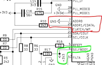
I have a PCB with the following connections : ADDR0 tied Low, ADDR1 tied to +3v3 through a 2k2 resistor, and also Selfboot enabled (pin tied to +3v3), as shown in the 1st image below.
When communicating using I2C, I see that the ADDR1 bit value is not taken into account : I need to write 0 for ADDR1 instead of 1 , even if I have a pullup to +3v3 on my PCB.
I discovered that, apparently, this is because when we are in Self boot mode (loading data from EEPROM at powerup), the 2 ADDRx inputs are unused and we need to use 0 for both when addressing the I2C, even if we tie the input to +3v3 on the PCB, as shown here on the datasheet Table15 (2nd image)
If my understanding above is correct, would it be possible to add a small note on the Table 11 of the datasheet, stating that ADDR1 is not used (0) when we are in SelfBoot mode ?
Thanks and regards,
Yoann
Audio Signal Processors
Datasheet/Specs
adau1401
ADAU1401 ; ADAU1701
SigmaDSP Audio Processors
datasheet
adau1701
ADDR1
Show More


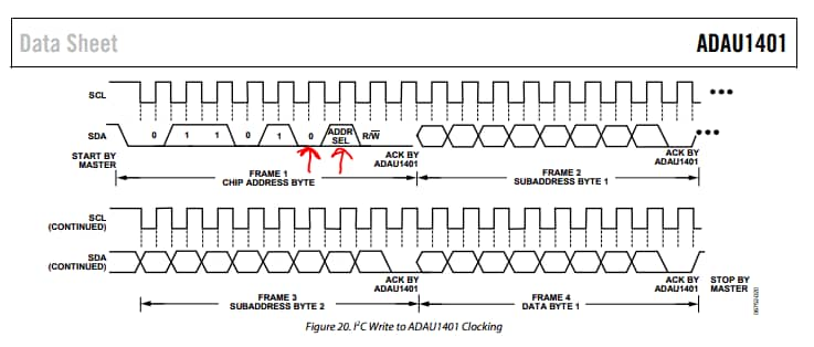
Also, when we look into the I2C waveforms of the datasheet, we can see that we have 0 on ADDR1, we just have a "ADDR SEL" for ADDR0 (the 2 red arrows) :
Regards,
Yoann
Please log in to reply.