Master Control Port XML works in realtime link-compiling but not after boot
Hi, I need a help with my SS project:
I'm using a Master Control Port Boot to write some register configuration to my ADC and DACs
When I use it in realtime link-compile-download, works very well, but when I burn it to memory, the program do not configure the converters.
I don't know why... I tried change the block to trigger and trig it with a pulse, but without sucess.
Ps.: The memory it's working, I tested with other programs
My project attached:
Thanks by advance
ADAU1466.rar
Audio Signal Processors
adau1452
adc
programming
software
xml_files
i2c
problem
i2s
parameters
xml
sigmastudio
SigmaDSP Audio Processors
SigmaDSP
dsp&processors
adau1462
selfboot
adau1466
Show More
No one has a guess? :,(
Just this to finish my project and start the real program
Hello IcaroViana2,
I tried to simulate your issue, but I can be able to self-boot the DSP and program external IC's from the master control port. I have modified your program and make it work for me. I will attach the program here. Please change the xml file for your IC and try and get back.
If this project also doesn't work, then send us your schematic of the master control port. It may be a hardware issue. I hope you followed the self-boot procedure given in the user manual properly since you said the normal booting is working fine.
Probe the I2C line and see what is sending out from the master control port.
I hope you are using I2C EEPROM? Since all your external IC's (converters) are configured for I2C. The same protocol should be used.
I have seen the register settings that your software sample rate is set for 96kHz, but CG1 output is set for 48KHz and start pulse register is set for base_fs * 2. Why don't you simply set N/M = 1/3 that will give you 96KHz and you can set the start pulse as base_fs. Although it's the same, I hope it makes things clear.
I guess your intended sample rate is 96KHz, so I have set everything at 96KHz and Serial ports also I set the same. So, change things like I2C/SPI, serial ports, etc., according to your need.
ADAU1466 modified.zip
Regards,
Harish
Hello Harishgowtham!
Thanks for your response
I tried your program and it didn't work again...
I'll give you some details and curiosities when I was testing some possibilities:
I resolve to see the i2c bus with my oscilloscope, so nothing was working, even the last program which was working just fine (all converters with default values, like i2s and not tdm)
So I removed the probe and everything worked again
Then I realized it might be a current problem like too much capacitance on the i2c bus.
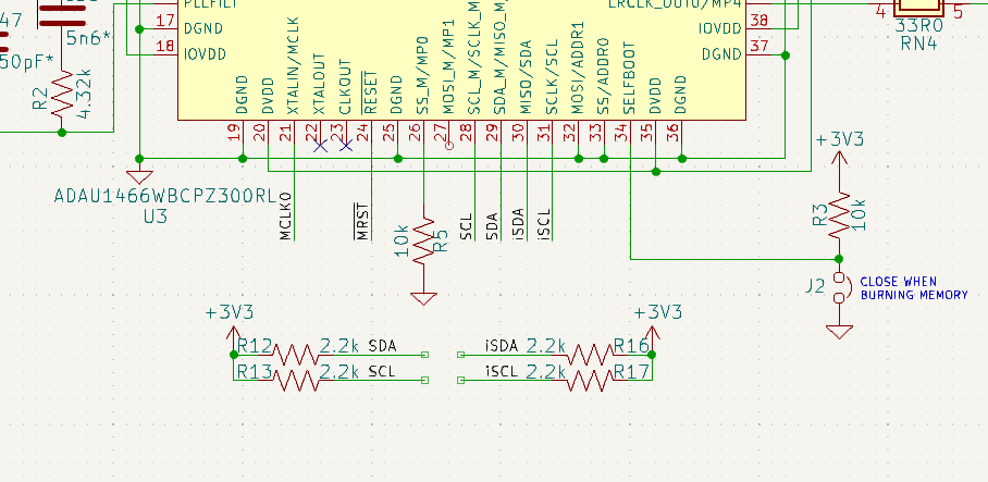
I reduced the pull-up resistors from 2k2 to 1k5 as my calculation was telling me - 2k max (about 170pF total)
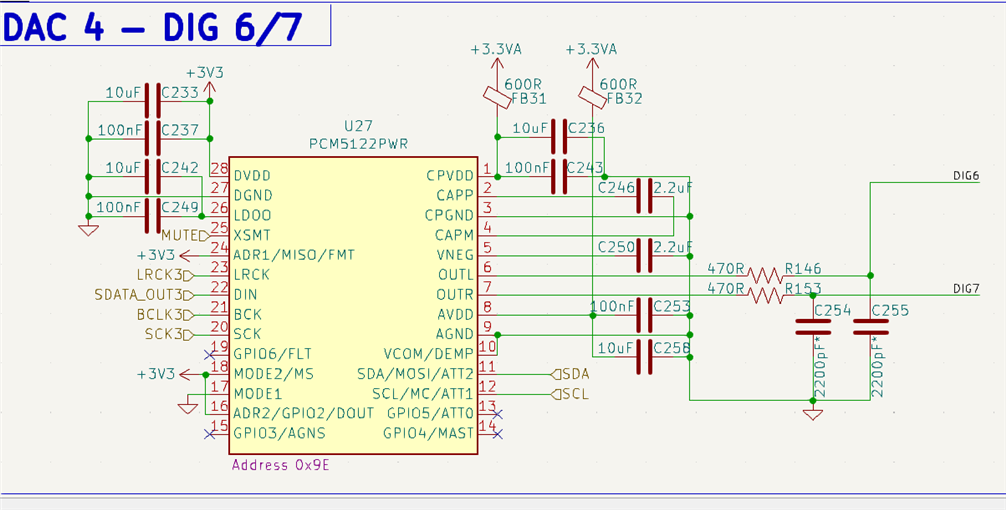
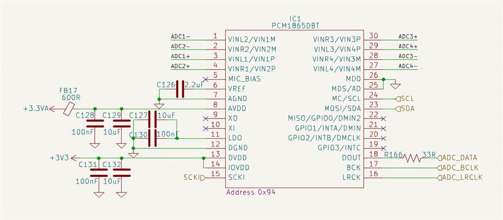
I'm using 1 PCM1865 and 4x PCM5122 on the bus, and also the memory (1Mbit I2C 24FC1025) and a PCA9536, just to control some leds.
The PCA is about 20 cm away from the motherboard.
More information:
When I don't use the Master Control Port everything works fine (default), but:
When I put a block to configure the ADC, the board current drops from 456mA to 395mA (60mA drop)
When I place two blocks to configure ADC and DAC, the board current drops from 456mA to 210mA (246mA drop)
I don't know why, strange behavior
4x of these
1x of these
i2c bus:
Does anyone have at least one little insight?
Hello,
IcaroViana2 said:
I resolve to see the i2c bus with my oscilloscope, so nothing was working, even the last program which was working just fine
While programming a single chip (ADC) by using one master control instance, Have you disconnected other slaves from the I2C bus?
So, you haven't encountered an I2C signal coming out from the master control port right?
IcaroViana2 said:
So I removed the probe and everything worked again
It seems like a hardware connection issue. Make sure your connections are stable.
IcaroViana2 said:
When I put a block to configure the ADC, the board current drops from 456mA to 395mA (60mA drop)
When I place two blocks to configure ADC and DAC, the board current drops from 456mA to 210mA (246mA drop)
I will get back to you in a while about this.
Regards,
Harish
Harishgowtham said:
While programming a single chip (ADC) by using one master control instance, Have you disconnected other slaves from the I2C bus?
So, you haven't encountered an I2C signal coming out from the master control port right?
All devices are soldered on the same board, I can't remove it to test :(
Now with smaller resistors, I can see signal writing on the memory, but the signal to configure devices whem boot, I can't (I don't know for sure, because it's too fast and my oscilloscope it's not too good)
Harishgowtham said:
It seems like a hardware connection issue. Make sure your connections are stable.
I used a 1k5 resistor to pull-up harder, now it's stable
Hey Harish, any news?
It still doesn't work... If anyone has any suggestions, let me know
Hello,
Sorry for the delay in response.
I have seen one thing in your I2C EEPROM's datasheet.
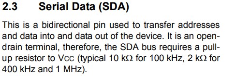
I see that your speed is 100KHz. So, try putting 10K ohm pull up resistor as mentioned above.
Is all of your slave devices connected in the I2C bus being powered up?
Please attach your EEPROM schematic if possible.
IcaroViana2 said:
but the signal to configure devices whem boot, I can't (I don't know for sure, because it's too fast and my oscilloscope it's not too good)
If possible, can you attach some of your scope shots? Please set a trigger and try to capture.
Regards,
Harish
Please log in to reply.